i added a delay(3) inside the loop to simulate other work and got the same problem.
Hello Sir,
Havent calibrated it yet, but I can surely answer, why youre getting 4095 ADC reading all the time.
-Since it is needed for calculating the RMS- Then the rest is just a linear transformation to get an output around 220 from the sensor output voltage. And we already know that the input voltage RMS is 220V. Doubts on how to use Github? Hi Sir In this code, first it finds the maximum measured value (peak voltage) and then converts it to RMS value.
So for (3.3V/Gnd) no AC -> 1.65 its good it means theres the offset and the module is working. #include Watch the tutorial for further explanations.
The wave form doesnt change at all.
As salam alaikm dear If I get this working, Ill post a .ino file back to you.
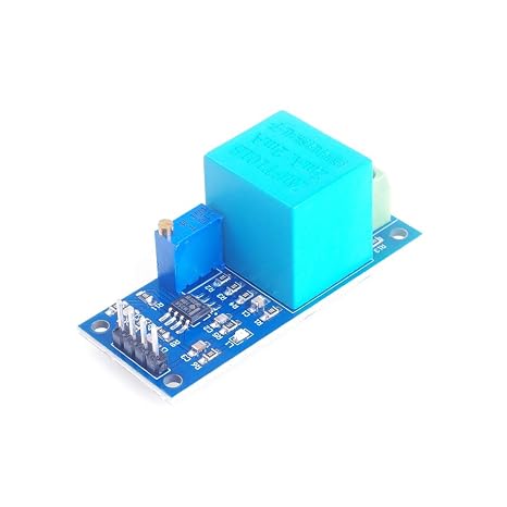
We are using the ZMPT101B.
Hi, First, the peak value of the sensor output voltage is divided by sqrt(2).
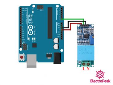
This is the whole wiring, and as mentionned Im using an 12832 OLED screen you can use it or no, the module is powred by 5v and delivers an analog signal. Hi. The potentiometer on this module is multi-turn.
float fBluePhaseVoltage; // stores the voltage in the Blue Phase.
inputStatsT.setWindowSecs( windowLength ); while( true ) { And heres how its derived: The graph of the sensor output voltage when it has the city electricity as its input is given as the result of the first code. inputStats.setWindowSecs( windowLength );
Mr. Gilmar exit status 1 The value for out put is sth between 0-5 V. in this situation if I connect the module to 120V and 230V, what we will be the value of output? HiLetgo 37 Sensors Assortment Kit 37 Sensors Kit Sensor Starter Kit for Arduino Raspberry pi Sensor kit 37 in 1 Robot Projects Starter Kits for Arduino Raspberry pi, Variety of Sensors for Your Electronic Projects, All customers get FREE Shipping on orders over $25 shipped by Amazon.
Serial.begin( 9600 ); // start the serial port Serial.print(fYellowPhaseVoltage); Hi, Check:Measure any AC voltage (250VAC) with ZMPT101B and ESP8266 12E with Android App / Adafruit IO MQTT. boards. Hi,
My programming is below , But the Ac Voltage measure is not right.
Serial.println(fBluePhaseVoltage); For the intercept and slope, you should modify them depending on your calibration, first dont forget to set the module potentiometer as I showed in the tutorial, just by observing the serial plotter until you get an acceptable shape. https://surtrtech.com/2019/12/11/measure-any-ac-current-with-acs712-and-arduino-lcd-oled/
Actually, no, it can only measure AC voltage.
Find anything that can be improved? I have a question about analog output. lcd.print(volts); When i print directly on serial monitor it give accurate volt but when i am using TM1637 Library and module to print the voltage it give us unstable voltage, i fund the reason is some delay on TM1637 library, Now what can i do for stable value with TM1637 and Filter library for stable value and sigma value, please help, Hi sir, thank you for this wonderful project. zmpt101b tegangan komponen  (+/-30Amp), ELEGOO Upgraded 37 in 1 Sensor Modules Kit with Tutorial Compatible with Arduino IDE UNO R3 MEGA Nano.
Im testing on a Particle.io Argon board, as this will send out messages via the Particle.io API, so I can get alerts when power is cut. AC_Voltage_Measuring:53:3: error: inputStats was not declared in this scope 2. at 3.3v, this time use (3.3V/GND), no AC voltage -> measured reading 1.65v lcd.clear(); In My team we are building a Eletric generator . Particle can also send short heartbeat messages, with data on voltage, stats, etc.
Mein was based on an code I made before to measure current so I had to readjust, Hi my problem is that it deos not work ESP32, I am trying to get voltage reading on ESP32.
but there is no change in this value even I connect or disconnect AC power.
*/, #include //Easy library to do the calculations, float testFrequency = 50; // test signal frequency (Hz)
arduino zmpt101b interfacing circuit electropeak
lcd.print(Voltimetro);
The problem is that when finished calibrating and supply a different voltage it gives back wrong readings. Hi, i tested it exactly as your code and it works pefectly, but now i want to run it inside a bigger project and i get a lot of noise (same hardware, more complex arduino code).
inputStats.input(iSensor); //log to Stats function
I actually have other stuff to do in the main loop() so did this way to slightly organize the code, but this does not work, I get reading 1.02, 0.97, 1.10 etc. current_Volts= current_Volts*(40.3231); //Further calibrations for the amplitude. thank you for your great article.
Serial.begin( 9600 ); // start the serial port
And we already know that the input voltage RMS is 220V. current_VoltsS = intercept + slope * inputStatsS.sigma(); //Calibartions for offset and amplitude
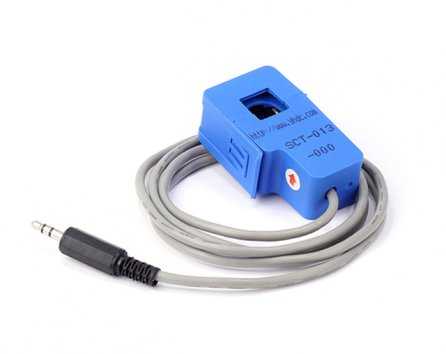
Hello! Do you have any suggestion? previousMillis = millis(); // update time. can i use this code with esp32?? current sensor arduino 30a invasive non max ac xbee sct transformer split core int SensorS = 1; //Sensor analog input, here it's A0 I am not sure but it does not work as signal-out value remain same. Also dont forget that the module delivers a sinewave signal not a continuous one, if you just use the serial monitor to see the values it will show strange different values, and it would be difficult to measure them when AC is on.
Serial.println(Serial started); HI DEAR float current_VoltsT; // Voltage.
I have powered ZMPT101B module with 5v. const int iBluePhaseSensorPin = 2; //Sensor analog input, pin A2 hello, has anyone tried this on 60Hz frequency to measure 220-240V?
How I check it as I do not have Arduino UNO with me. All you need to change is to replace A0 in line 28 and 29 with any of the pins of ESP32.
Arduino IDE and install it from there.
which can be 2.5, 6 or 11 dB.
Hi, is there any change in the code for standard 120v. You can see that the maximum voltage is somewhere around 600. current_Volts= current_Volts*(40.3231); if you understand one youll be able to do the others, Thank you Sir, How are you current_VoltsT = current_VoltsT*(40.3231); //Further calibrations for the amplitude, //current_VoltsR= current_VoltsR*(42); //Further calibrations for the amplitude, Serial.print( "\tVoltage (R): " );
Would you have any tip to help me?
I have a 120V 60Hz power network. So, Im afraid its not suitable for your application. And if possible its better to contact me on facebook page, Can you tell me, from your code , where you got the values below ? When the module is powred (with 5v) it will send 2.5V (512) to the Arduino (when theres no AC power to its input) and when you add an AC power source the voltage will be around 0-5V (0-1023) these values depend on the board ADC,for Arduino UNO its from 0-1023 10 bits).
Any thoughts of how to do this with ZMPT ?
Hi Yassine. Can you help me in the project? when I pull out cable from shifter-To-ESP32(pin15), there is zero value on it. But for the other thing (doing other stuffs beside measuring) Ill start working on it as soon as possible and if I succeded, a little video will be up with calibration summary too. If I understood you correctly, First I set the Slope=0, put no voltage to the module, and adjust intercept, so the value given in the serial monitor to be 0.
but it is same.
I also note that the value you get as 511 is different when we consider esp32 since its ADC is 4096..
lcd.begin(16, 2); void loop() { Hi, im beginner for high voltage thing, can anyone tell me using this ZMPT101B sensor. RunningStatistics inputStatsR; //Easy life lines, actual calculation of the RMS requires a load of coding Im doing exact the same thing and trying to make ZMPT101B work with ESP32. I want measure both current with(ac712)+ voltage with (zpmt) . 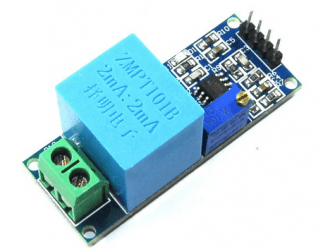 Because you should remove it if youre using the code in another project. how the following formula is derived>?can you please explain? Your recently viewed items and featured recommendations, Select the department you want to search in, Gikfun Mini Solder-able Breadboard Gold Plated Finish Proto Board PCB for Arduino Electronic DIY (Pack of 5PCS) GK1009, Gikfun Prototype Shield DIY KIT for Arduino UNO R3 Mega 328P (Pack of 3 Sets) Ek1038x3, Gikfun Prototype PCB Breadboard for Arduino UNO R3 Shield Board (Pack of 5pcs) GK1011.
If nothing is connected to the module inputs (module input is 0 volts), your diagram will show a number around 512 (i.e. https://github.com/Abdurraziq/ZMPT101B-arduino const int iRedPhaseSensorPin = 0; //Sensor analog input, pin A0 what is my next step to calibrating ? or maybe you would recommend some other way to do it instead?
Test first with only this line Serial.println(analogRead(A0)); add the necessary things like void setup, serial begin., upload the code to the board and open the serial plotter in Arduino IDE, youll see values around 1.65V (2046) maybe.