This means they have two flow pipe connections and can switch into two different positions. View all of your saved projects as well as your order history in the Customer Portal. Fax: 314.647.5736, CARR LANE MANUFACTURING
Accumulators are used to store hydraulic energy and to absorb shock in a hydraulic system. In the cutaway drawing, the spring is shown as a series of dots.
Copyright 2022 Carr Lane Manufacturing. But if you select a valve spool that remains open P, A, and B to T during switchover, then no damaging high pressures will occur. symbols hydraulic mechanical engineering circuit pnuematic google chart difference between valve result systems Pilot operated valves are required for system flows above 30-40 gpm, and these valves can be illustrated two ways. Your Distrubtor Portal Account has been created.Please check your email for a link to verify your account. I believe your description of the figure is incorrect. Each uses symbology differently because their valves are manufactured and applied individually based on the needs of their industries. It's not always added to a relief valve schematic symbol, since many relief valves are cartridge valves and do not have a separate manifold. This format is commonly used with fixed displacement pumps so that there is no pressure on the pump when it is not required. The operators are little symbols at the left and right sides of the valve symbol, which indicate how the spool is moved. There are auxiliary functions to every directional control valve, and these add utility to the valve. The above symbol shows the typical 3-position directional valve with the internal lineation removed. What matters is that the a actuator operates the a envelope, for example.
The number of blows varies. Copyright Engineering Adventures , all rights reserved. Hydraulic valves have a tendency to be the most complex components of a hydraulic system, and their schematic symbols are just as complex. Sometimes it is vital to know whether a particular flow line will remain open or shut while the valve is switched. Electro-Pneumatic Regulator & Flow Controller Design, Industrial shock absorbers: The sizing process, A creative approach to mobile-hydraulic controls. For more information about reading hydraulic and pneumatic circuit diagrams, read the next article in this series which describes sample hydraulic circuits, or contact your Valmet representative. Some valves can be pressure and/or temperature compensating.
4200 CARR LANE CT. P.O. It controls the actuators position and direction by controlling the fluid flow into the actuator. For the strictly manually operation, the lever actuator makes sense, and can be seen in forms varying from the one above. A detent mechanism can be added to either side of a valve to create maintained flow such as is required for some motor or clamping functions.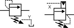 It is used in conjunction with load holding or motion control valves, which themselves necessitate draining of their spring chambers, a function that wouldnt occur with a closed center. Through-center valves are not used with industrial applications, and 3-way valves are only common with cartridge valves, for example. When the pilot line in a pilot-to-close valve is pressurized, the check valve is closed, blocking flow in both directions. Note how the hydraulic pilot is shown as a solid triangle although if this was a pneumatic pilot it would be shown as a clear triangle. This article is the third in my series on hydraulic symbology, this time going beyond the basics to discuss symbols in higher detail. Yes, I would like to receive occasional news and product updates from Carr Lane Manufacturing. pneumatic symbols camozzi tech The bottom symbol shows a three-way three position valve that is hydraulically operated. All symbols show four-way three position valves. On this page, Carr Lane ROEMHELD provides a comprehensive table outlining the definitions of each symbol used in a hydraulic diagram. This is an open center. In the schematic, the zig-zag line is the spring. The way to decipher a direction control valve symbol is as follows: The flow control valve is used to control the flow rate as well as the speed of the actuator. Please enter the email address associated with your account and we will send you an email containing your password. A pressure relief valve is a NC (normally closed) type safety valve which operates when system pressure increases above a maximum working pressure.
  We use JavaScript to power our learning media, so you'll need to turn JavaScript on before you can use LunchBox Sessions. The lower end (suction side) of a pump is connected to the hydraulic reservoir, the upper end is connected to the remaining circuit. Please login or retrieve your credentials. This is not necessarily the case in more complex valves. hydraulic symbols tools control valves fluid engineering mechanical chart circuit tool system symbol pneumatic schematic circuits names library valve classes However, this configuration could be very dangerous if stopping the load from falling is the main concern. Firing the a coil would provide flow paths from P to B and A to T, while firing of the b coil would allow flow from P to A and B to T. Other common center conditions for valves are shown above. (In other cutaway graphics, springs are sometimes drawn with diagonal lines connecting the dots, representing the coil of the spring.). Several Types of Engineering Projects Where Using CAD is a Must, Maya vs Blender: Feature by Feature Comparison (2022), Video of the Day: Fastest Train Ever Built, Drill size chart inch and metric | Downloadable PDF, Needle Valves function and selection criteria. Always growing, always educating Welcome to the 11th edition of the fluid power handbook. Fluid Power World covers pneumatics, mobile hydraulics and industrial hydraulics. valve symbol directional symbols flow hydraulic operated pilot hydraulically probably bottom complete shows would hyd princip glossary texasfinaldrive Your Customer Portal Account has been created.Please check your email for a link to verify your account. Pressure reducing valves are used to reduce the pressure in individual circuits. Request A Catalog
valve hydraulic symbols control directional symbol valves center closed position circuit flow hydraulics pressure google blocked spring ports pdf four A and B are the work ports that connect to the actuator, P comes from the pump and T returns to tank. If you need help, email us at support@lunchboxsessions.com. The open center valve provides the same benefits as the float spool, but can be used with fixed displacement pumps. valve symbols pneumatic control valves port hydraulic types introduction various figure 6d shown The left side of the actuator is connected to a reservoir meaning the actuator will move towards the left side. The dark upper triangle in these hydraulic symbols indicates fluid going out of the system and hence represents a pump. When the electrical solenoids are operated the spool position moves to either the right or left-hand position, allowing the different symbol logic to be employed. Fluid power systems are comprised of components that include pumps, cylinders,, Copyright 2022 WTWH Media LLC. Carr Lane Distributor Portal Account Registration. These symbols show a range of crossover conditions for the same style of 4 way 3 position valve. The fourth and fifth positions are purely what happens at the point at which the valve switches. The dashed line indicates that the system pressure acts against spring force for valve actuation. Modular stack valves are a method of creating complete circuits using CETOP ISO valves, but their symbology is different from normally drawn circuits. Any pressure in the A or B lines remains trapped. The bottom symbol shows a hydraulically operated valve, but in this case, flow can only pass in one direction because the spring chamber is connected to the low pressure, return line connection.
We use JavaScript to power our learning media, so you'll need to turn JavaScript on before you can use LunchBox Sessions. The lower end (suction side) of a pump is connected to the hydraulic reservoir, the upper end is connected to the remaining circuit. Please login or retrieve your credentials. This is not necessarily the case in more complex valves. hydraulic symbols tools control valves fluid engineering mechanical chart circuit tool system symbol pneumatic schematic circuits names library valve classes However, this configuration could be very dangerous if stopping the load from falling is the main concern. Firing the a coil would provide flow paths from P to B and A to T, while firing of the b coil would allow flow from P to A and B to T. Other common center conditions for valves are shown above. (In other cutaway graphics, springs are sometimes drawn with diagonal lines connecting the dots, representing the coil of the spring.). Several Types of Engineering Projects Where Using CAD is a Must, Maya vs Blender: Feature by Feature Comparison (2022), Video of the Day: Fastest Train Ever Built, Drill size chart inch and metric | Downloadable PDF, Needle Valves function and selection criteria. Always growing, always educating Welcome to the 11th edition of the fluid power handbook. Fluid Power World covers pneumatics, mobile hydraulics and industrial hydraulics. valve symbol directional symbols flow hydraulic operated pilot hydraulically probably bottom complete shows would hyd princip glossary texasfinaldrive Your Customer Portal Account has been created.Please check your email for a link to verify your account. Pressure reducing valves are used to reduce the pressure in individual circuits. Request A Catalog
valve hydraulic symbols control directional symbol valves center closed position circuit flow hydraulics pressure google blocked spring ports pdf four A and B are the work ports that connect to the actuator, P comes from the pump and T returns to tank. If you need help, email us at support@lunchboxsessions.com. The open center valve provides the same benefits as the float spool, but can be used with fixed displacement pumps. valve symbols pneumatic control valves port hydraulic types introduction various figure 6d shown The left side of the actuator is connected to a reservoir meaning the actuator will move towards the left side. The dark upper triangle in these hydraulic symbols indicates fluid going out of the system and hence represents a pump. When the electrical solenoids are operated the spool position moves to either the right or left-hand position, allowing the different symbol logic to be employed. Fluid power systems are comprised of components that include pumps, cylinders,, Copyright 2022 WTWH Media LLC. Carr Lane Distributor Portal Account Registration. These symbols show a range of crossover conditions for the same style of 4 way 3 position valve. The fourth and fifth positions are purely what happens at the point at which the valve switches. The dashed line indicates that the system pressure acts against spring force for valve actuation. Modular stack valves are a method of creating complete circuits using CETOP ISO valves, but their symbology is different from normally drawn circuits. Any pressure in the A or B lines remains trapped. The bottom symbol shows a hydraulically operated valve, but in this case, flow can only pass in one direction because the spring chamber is connected to the low pressure, return line connection.
Thank You! This spool is common on gear pump systems operating cylinders with no work-holding requirement. Necessary cookies are absolutely essential for the website to function properly. Gauges are used to measure the oil pressure at a given point in the system. When using valves that switch pressure lines, without a direct, low pressure, return line connection it is important to make sure that the valves solenoid and spring chambers are rated for the maximum pressure they may see. The most commonly used hydraulic symbols are as follows: Hydraulic cylinders can be categorized as single acting cylinders and double acting cylinders. Learn About the Carr Lane Customer Portal, Basic Symbols Representing Hydraulic Components. By continuing to use this website, you are giving consent to cookies being used. The 'two position' means that it has two switched positions i.e. Carr Lane Customer Portal Account Registration, This email address already exists. A technical comparison: Performance of pneumatic cylinders and electric rod actuators, Quick Connect Couplings: A Critical Component in Hydraulic Systems. There are a number of ways to control the flow: Check valve allows the fluid to pass only in one direction and restricts flow in the opposite direction. Pressure switches are use to detect a pressure rise or fall through a set pressure point.
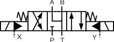
In the figure, the DCV is in its 1st position and hence pressurized liquid will flow towards the right side of actuator. A safe pressure level is maintained using the pressure relief valve which is connected after the pump. This valve also has two end springs to return the spool to the centre position when no pilot signal is available. Rather then simply being referred to by a number, the ports on a directional control valve are labelled to indicate the purpose of the port. Triangular arrows represent the direction fluid takes in the pump or motor. Browse By Model Flow fuses are normally open valves which close if the pressure difference between the inlet and outlet valves is too high compared to the design setting. What happens in between has consequences on system performance. One use of a level switch is to detect when the oil in a reservoir is reduced to a minimum operating level. Heat exchangers are used to remove heat from the circulating oil in the hydraulic system. Fluid actuators are used to convert fluid energy into mechanical linear motion. Check valves are one way valves, allowing flow in only one direction. It was previously common to do factory automation by way of directional control valves, but the practice is less common in the current electronic age. The position of flow control valve will lead to varied system behavior an arrow representing the adjustable flow control. Water modulating valves are used for controlling the oil temperature in the reservoir automatically by controlling the volume of water going through the heat exchanger. Motors are often bi-rotational and have triangles at both the top and bottom of the circle. Note:Arrow is not part of the symbol. Note how the valves all have two springs so that with no signal to the valve, it will sit in its central, standby position. Electric solenoid operation is by far the most common for industrial valves, and is depicted by the same basic actuator rectangle with a diagonal line. Every square box indicates one valve position. Not all valves will operate or work safely without a low-pressure drain signal. 4200 CARR LANE CT. P.O. What do circles, semi circles, squares, rectangles, diamonds and lines represent in hydraulic schematics? valve hydraulic sequence symbol symbols hyd pressure relief adjustable princip The pump will be variable displacement or with some sort of automatic unloading function. pneumatic symbols valve operator explained pneumatics sensors It is our intent that any communication with you will be purposeful and useful. When activated the left-hand box would be connected to the pipes and flow could pass through the valve. hello The P port is open to tank, but the A and B work ports are blocked. Save to My ProjectBuild & Manage Projects On-Site.Your Parts Your Way!Click the Save to My Project button to build a saved search history that you can use to build a project or parts list. The left position is the reverse of the right position, with the pump port, Relate symbol elements to actual valve components. Let's look at each of the 3 positions in this valve, in both schematic and graphic cutaway.
wondered if youd be willing to give me some guidence please, 2020 All rights Reserved. The actuators, in function, are the electric or mechanical devices that shift the valve out of neutral to any of the operational envelopes. The top symbol shows a two-position valve that is switched by a mechanical roller. We also use third-party cookies that help us analyze and understand how you use this website. Proportional valves are electrically controlled hydraulic valves. The central position is a neutral position and various neutral positions are available depending upon the application. Dotted lines indicate pilot signals and drains
Let's take a look at something a little more complex: a four port, three position directional control valve. Armed with knowledge of how basic hydraulic components are represented in the hydraulic circuit; one can understand a wide range of different hydraulic symbols, representing components performing similar tasks with minor modifications. How is it possible to have three distinct positions with a single coil? When present in a hydraulic schematic, you will see dashed pilot lines routed to the pilot operators. directional symbols valve valves way control hydraulic flow three The solenoid operators indicate that the valve can be operated electrically. The A, B and T lines are connected together in the centre position to avoid pressure build-up on the actuator. A spring is used to return to a neutral position. symbols hydraulic pneumatic symbol valve engineering schematic result kevy library cf circuit fluid valves systems If we break down the symbols, you'll see they are very straightforward. "Metered in" control means that the flow controls are controlling the fluid into the actuator, "metered out" is controlling the fluid out of the actuator. Hydraulic power is based on Pascals Principle; pressure exerted on a fluid is distributed equally, applied pressure is equal to desired pressure, The most common hydraulic symbols are represented by the ISO 1219-1:2012 standard, Adjusting the flow rate of fluid in a hydraulic system will directly impact the output; temperature and pressure indicators are used to create a safety mechanism, Hydraulic systems convert electrical and/or mechanical energy into hydraulic energy. Thank You! To take advantage of these features, just create a customer account! This means they have three flow pipe connections.
Copyright 2022 Carr Lane Manufacturing. But if you select a valve spool that remains open P, A, and B to T during switchover, then no damaging high pressures will occur. symbols hydraulic mechanical engineering circuit pnuematic google chart difference between valve result systems Pilot operated valves are required for system flows above 30-40 gpm, and these valves can be illustrated two ways. Your Distrubtor Portal Account has been created.Please check your email for a link to verify your account. I believe your description of the figure is incorrect. Each uses symbology differently because their valves are manufactured and applied individually based on the needs of their industries. It's not always added to a relief valve schematic symbol, since many relief valves are cartridge valves and do not have a separate manifold. This format is commonly used with fixed displacement pumps so that there is no pressure on the pump when it is not required. The operators are little symbols at the left and right sides of the valve symbol, which indicate how the spool is moved. There are auxiliary functions to every directional control valve, and these add utility to the valve. The above symbol shows the typical 3-position directional valve with the internal lineation removed. What matters is that the a actuator operates the a envelope, for example.
The number of blows varies. Copyright Engineering Adventures , all rights reserved. Hydraulic valves have a tendency to be the most complex components of a hydraulic system, and their schematic symbols are just as complex. Sometimes it is vital to know whether a particular flow line will remain open or shut while the valve is switched. Electro-Pneumatic Regulator & Flow Controller Design, Industrial shock absorbers: The sizing process, A creative approach to mobile-hydraulic controls.
For more information about reading hydraulic and pneumatic circuit diagrams, read the next article in this series which describes sample hydraulic circuits, or contact your Valmet representative. Some valves can be pressure and/or temperature compensating. 4200 CARR LANE CT. P.O. It controls the actuators position and direction by controlling the fluid flow into the actuator. For the strictly manually operation, the lever actuator makes sense, and can be seen in forms varying from the one above. A detent mechanism can be added to either side of a valve to create maintained flow such as is required for some motor or clamping functions.
It is used in conjunction with load holding or motion control valves, which themselves necessitate draining of their spring chambers, a function that wouldnt occur with a closed center. Through-center valves are not used with industrial applications, and 3-way valves are only common with cartridge valves, for example. When the pilot line in a pilot-to-close valve is pressurized, the check valve is closed, blocking flow in both directions. Note how the hydraulic pilot is shown as a solid triangle although if this was a pneumatic pilot it would be shown as a clear triangle. This article is the third in my series on hydraulic symbology, this time going beyond the basics to discuss symbols in higher detail. Yes, I would like to receive occasional news and product updates from Carr Lane Manufacturing. pneumatic symbols camozzi tech The bottom symbol shows a three-way three position valve that is hydraulically operated. All symbols show four-way three position valves. On this page, Carr Lane ROEMHELD provides a comprehensive table outlining the definitions of each symbol used in a hydraulic diagram. This is an open center. In the schematic, the zig-zag line is the spring. The way to decipher a direction control valve symbol is as follows: The flow control valve is used to control the flow rate as well as the speed of the actuator. Please enter the email address associated with your account and we will send you an email containing your password. A pressure relief valve is a NC (normally closed) type safety valve which operates when system pressure increases above a maximum working pressure.  We use JavaScript to power our learning media, so you'll need to turn JavaScript on before you can use LunchBox Sessions. The lower end (suction side) of a pump is connected to the hydraulic reservoir, the upper end is connected to the remaining circuit. Please login or retrieve your credentials. This is not necessarily the case in more complex valves. hydraulic symbols tools control valves fluid engineering mechanical chart circuit tool system symbol pneumatic schematic circuits names library valve classes However, this configuration could be very dangerous if stopping the load from falling is the main concern. Firing the a coil would provide flow paths from P to B and A to T, while firing of the b coil would allow flow from P to A and B to T. Other common center conditions for valves are shown above. (In other cutaway graphics, springs are sometimes drawn with diagonal lines connecting the dots, representing the coil of the spring.). Several Types of Engineering Projects Where Using CAD is a Must, Maya vs Blender: Feature by Feature Comparison (2022), Video of the Day: Fastest Train Ever Built, Drill size chart inch and metric | Downloadable PDF, Needle Valves function and selection criteria. Always growing, always educating Welcome to the 11th edition of the fluid power handbook. Fluid Power World covers pneumatics, mobile hydraulics and industrial hydraulics. valve symbol directional symbols flow hydraulic operated pilot hydraulically probably bottom complete shows would hyd princip glossary texasfinaldrive Your Customer Portal Account has been created.Please check your email for a link to verify your account. Pressure reducing valves are used to reduce the pressure in individual circuits. Request A Catalog
valve hydraulic symbols control directional symbol valves center closed position circuit flow hydraulics pressure google blocked spring ports pdf four A and B are the work ports that connect to the actuator, P comes from the pump and T returns to tank. If you need help, email us at support@lunchboxsessions.com. The open center valve provides the same benefits as the float spool, but can be used with fixed displacement pumps. valve symbols pneumatic control valves port hydraulic types introduction various figure 6d shown The left side of the actuator is connected to a reservoir meaning the actuator will move towards the left side. The dark upper triangle in these hydraulic symbols indicates fluid going out of the system and hence represents a pump. When the electrical solenoids are operated the spool position moves to either the right or left-hand position, allowing the different symbol logic to be employed. Fluid power systems are comprised of components that include pumps, cylinders,, Copyright 2022 WTWH Media LLC. Carr Lane Distributor Portal Account Registration. These symbols show a range of crossover conditions for the same style of 4 way 3 position valve. The fourth and fifth positions are purely what happens at the point at which the valve switches. The dashed line indicates that the system pressure acts against spring force for valve actuation. Modular stack valves are a method of creating complete circuits using CETOP ISO valves, but their symbology is different from normally drawn circuits. Any pressure in the A or B lines remains trapped. The bottom symbol shows a hydraulically operated valve, but in this case, flow can only pass in one direction because the spring chamber is connected to the low pressure, return line connection.
We use JavaScript to power our learning media, so you'll need to turn JavaScript on before you can use LunchBox Sessions. The lower end (suction side) of a pump is connected to the hydraulic reservoir, the upper end is connected to the remaining circuit. Please login or retrieve your credentials. This is not necessarily the case in more complex valves. hydraulic symbols tools control valves fluid engineering mechanical chart circuit tool system symbol pneumatic schematic circuits names library valve classes However, this configuration could be very dangerous if stopping the load from falling is the main concern. Firing the a coil would provide flow paths from P to B and A to T, while firing of the b coil would allow flow from P to A and B to T. Other common center conditions for valves are shown above. (In other cutaway graphics, springs are sometimes drawn with diagonal lines connecting the dots, representing the coil of the spring.). Several Types of Engineering Projects Where Using CAD is a Must, Maya vs Blender: Feature by Feature Comparison (2022), Video of the Day: Fastest Train Ever Built, Drill size chart inch and metric | Downloadable PDF, Needle Valves function and selection criteria. Always growing, always educating Welcome to the 11th edition of the fluid power handbook. Fluid Power World covers pneumatics, mobile hydraulics and industrial hydraulics. valve symbol directional symbols flow hydraulic operated pilot hydraulically probably bottom complete shows would hyd princip glossary texasfinaldrive Your Customer Portal Account has been created.Please check your email for a link to verify your account. Pressure reducing valves are used to reduce the pressure in individual circuits. Request A Catalog
valve hydraulic symbols control directional symbol valves center closed position circuit flow hydraulics pressure google blocked spring ports pdf four A and B are the work ports that connect to the actuator, P comes from the pump and T returns to tank. If you need help, email us at support@lunchboxsessions.com. The open center valve provides the same benefits as the float spool, but can be used with fixed displacement pumps. valve symbols pneumatic control valves port hydraulic types introduction various figure 6d shown The left side of the actuator is connected to a reservoir meaning the actuator will move towards the left side. The dark upper triangle in these hydraulic symbols indicates fluid going out of the system and hence represents a pump. When the electrical solenoids are operated the spool position moves to either the right or left-hand position, allowing the different symbol logic to be employed. Fluid power systems are comprised of components that include pumps, cylinders,, Copyright 2022 WTWH Media LLC. Carr Lane Distributor Portal Account Registration. These symbols show a range of crossover conditions for the same style of 4 way 3 position valve. The fourth and fifth positions are purely what happens at the point at which the valve switches. The dashed line indicates that the system pressure acts against spring force for valve actuation. Modular stack valves are a method of creating complete circuits using CETOP ISO valves, but their symbology is different from normally drawn circuits. Any pressure in the A or B lines remains trapped. The bottom symbol shows a hydraulically operated valve, but in this case, flow can only pass in one direction because the spring chamber is connected to the low pressure, return line connection. 
Thank You! This spool is common on gear pump systems operating cylinders with no work-holding requirement. Necessary cookies are absolutely essential for the website to function properly. Gauges are used to measure the oil pressure at a given point in the system. When using valves that switch pressure lines, without a direct, low pressure, return line connection it is important to make sure that the valves solenoid and spring chambers are rated for the maximum pressure they may see. The most commonly used hydraulic symbols are as follows: Hydraulic cylinders can be categorized as single acting cylinders and double acting cylinders. Learn About the Carr Lane Customer Portal, Basic Symbols Representing Hydraulic Components. By continuing to use this website, you are giving consent to cookies being used. The 'two position' means that it has two switched positions i.e. Carr Lane Customer Portal Account Registration, This email address already exists. A technical comparison: Performance of pneumatic cylinders and electric rod actuators, Quick Connect Couplings: A Critical Component in Hydraulic Systems. There are a number of ways to control the flow: Check valve allows the fluid to pass only in one direction and restricts flow in the opposite direction. Pressure switches are use to detect a pressure rise or fall through a set pressure point.
In the figure, the DCV is in its 1st position and hence pressurized liquid will flow towards the right side of actuator. A safe pressure level is maintained using the pressure relief valve which is connected after the pump. This valve also has two end springs to return the spool to the centre position when no pilot signal is available. Rather then simply being referred to by a number, the ports on a directional control valve are labelled to indicate the purpose of the port. Triangular arrows represent the direction fluid takes in the pump or motor. Browse By Model Flow fuses are normally open valves which close if the pressure difference between the inlet and outlet valves is too high compared to the design setting. What happens in between has consequences on system performance. One use of a level switch is to detect when the oil in a reservoir is reduced to a minimum operating level. Heat exchangers are used to remove heat from the circulating oil in the hydraulic system. Fluid actuators are used to convert fluid energy into mechanical linear motion. Check valves are one way valves, allowing flow in only one direction. It was previously common to do factory automation by way of directional control valves, but the practice is less common in the current electronic age. The position of flow control valve will lead to varied system behavior an arrow representing the adjustable flow control. Water modulating valves are used for controlling the oil temperature in the reservoir automatically by controlling the volume of water going through the heat exchanger. Motors are often bi-rotational and have triangles at both the top and bottom of the circle. Note:Arrow is not part of the symbol. Note how the valves all have two springs so that with no signal to the valve, it will sit in its central, standby position. Electric solenoid operation is by far the most common for industrial valves, and is depicted by the same basic actuator rectangle with a diagonal line. Every square box indicates one valve position. Not all valves will operate or work safely without a low-pressure drain signal. 4200 CARR LANE CT. P.O. What do circles, semi circles, squares, rectangles, diamonds and lines represent in hydraulic schematics? valve hydraulic sequence symbol symbols hyd pressure relief adjustable princip The pump will be variable displacement or with some sort of automatic unloading function. pneumatic symbols valve operator explained pneumatics sensors It is our intent that any communication with you will be purposeful and useful. When activated the left-hand box would be connected to the pipes and flow could pass through the valve. hello The P port is open to tank, but the A and B work ports are blocked. Save to My ProjectBuild & Manage Projects On-Site.Your Parts Your Way!Click the Save to My Project button to build a saved search history that you can use to build a project or parts list. The left position is the reverse of the right position, with the pump port, Relate symbol elements to actual valve components. Let's look at each of the 3 positions in this valve, in both schematic and graphic cutaway.
wondered if youd be willing to give me some guidence please, 2020 All rights Reserved. The actuators, in function, are the electric or mechanical devices that shift the valve out of neutral to any of the operational envelopes. The top symbol shows a two-position valve that is switched by a mechanical roller. We also use third-party cookies that help us analyze and understand how you use this website. Proportional valves are electrically controlled hydraulic valves. The central position is a neutral position and various neutral positions are available depending upon the application. Dotted lines indicate pilot signals and drains
Let's take a look at something a little more complex: a four port, three position directional control valve. Armed with knowledge of how basic hydraulic components are represented in the hydraulic circuit; one can understand a wide range of different hydraulic symbols, representing components performing similar tasks with minor modifications. How is it possible to have three distinct positions with a single coil? When present in a hydraulic schematic, you will see dashed pilot lines routed to the pilot operators. directional symbols valve valves way control hydraulic flow three The solenoid operators indicate that the valve can be operated electrically. The A, B and T lines are connected together in the centre position to avoid pressure build-up on the actuator. A spring is used to return to a neutral position. symbols hydraulic pneumatic symbol valve engineering schematic result kevy library cf circuit fluid valves systems If we break down the symbols, you'll see they are very straightforward. "Metered in" control means that the flow controls are controlling the fluid into the actuator, "metered out" is controlling the fluid out of the actuator. Hydraulic power is based on Pascals Principle; pressure exerted on a fluid is distributed equally, applied pressure is equal to desired pressure, The most common hydraulic symbols are represented by the ISO 1219-1:2012 standard, Adjusting the flow rate of fluid in a hydraulic system will directly impact the output; temperature and pressure indicators are used to create a safety mechanism, Hydraulic systems convert electrical and/or mechanical energy into hydraulic energy. Thank You! To take advantage of these features, just create a customer account! This means they have three flow pipe connections.