Serial Port setup in Raspberry Pi OSUsing the UART serial port. Disabling the Serial Login Shell (alternative method) To disable the serial login shell without using raspi-config, you can use the following steps. Notes for the Raspberry Pi 3 Model B, B+, 4 and Raspberry Pi Zero W: The Raspberry Pi 3 Model B, B+, 4 and Raspberry Pi Zero W contain two Using the PL011 UART port.  Creating A Serial Link Via Bluetooth To A PC Running Windows.
  ls. Serial communication between Raspberry Pi 4 and Windows 10 PC. NOTE FOR RASPBERRY PI 3: The Raspberry pi 3 has changed things a bit and you might need to add the option enable_uart=1 at the end of /boot/config.txt (see this post by a Pi Engineer) Connection to a PC. Use command python -m serial.tools.miniterm, then enter device port and receive port data on screen. EIGHTBITS s. stopbits = serial. Open the Windows Control Panel. In search box, type "Bluetooth", and then click "Change Bluetooth settings".
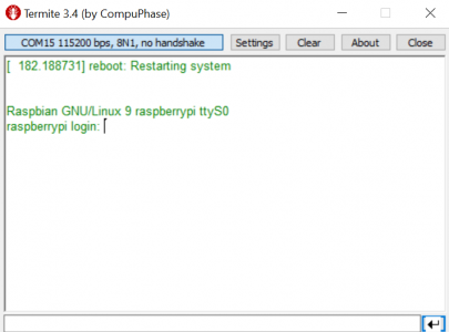
 1-2.
1-2.
Navigate to the Interfacing Options. 3.
My Raspberry Pi Pico-based Motorola 6809 emulator uses the RP2040s built-in serial-over-USB functionality to receive machine code sent from a host computer. Plug it in to your Raspberry Pi via USB. sudo raspi-config 2. bit by bit. Change to serial directory and list out the contents. The loop on the Pico in main.py should read it and display it on the LCD. Have a look at this Question and solution : such as #q355954, #q104086, #q315600, #q311032, #q262983, #q305764, #q76279, #q364122 and #q86456. Includes a PCBA and Pin Header cable for connecting with Pi GPIO The following picture shows which pins have to be connected in which way so that the communication can be done via the serial interface of the ESP32-CAM module 8:43 PM ESP32, ESP8266, nRF24L01, Orange Pi, Raspberry Pi, 1 54 Inch Epaper Module E paper E Ink EInk Display Screen SPI STOPBITS_ONE) Bytes are sent from your device to your computer at a set frequency.
 Also, before posting a question on Stack Exchange, look up what you are trying to do on google. Wiring 1-1.
  Hope you find the video quite helpful. PARITY_NONE, stopbits = serial. Connect jumper wires to USB-Serial cable for Tx, Rx, and GND. That way you can run Thonny or other IDE and see what is going on while the PC can communicate with the program being run and debugged.
 The user_t and password_t must be the same as that set in the previous chapter when securing the MQTT broker communication in Raspberry PI 3 Model B. Arduino Bidirectional Serial Communication with Raspberry Pi Eli the Computer Guy *NEW, Arduino - Serial Communication You can send data to a Raspberry Pi from an Arduino, have the Pi compute the data and use intelligence to send the Arduino a command. Use CTRL+] to close connection: pi @ raspberrypi: ~ $ python -m serial. miniterm. To connect from the Pi to the Pico, there are three options: Direct USB-to-USB. USB-TTL to Rx/Rx. Direct Tx/Rx Pins. Use a USB converter to connect the serial to the Raspberry Pi To begin, connect the TTL to USB converter to your Raspberry Pi board.
Then plug the Raspberry Pi supply and connect the converter to your PC.
Sorted by: 1. Connect USB-Serial cable to USB port on PC 2. 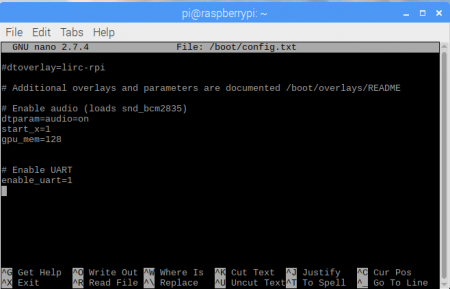 Step 2. Exception in thread rx: Traceback (most recent call last): File "/usr/lib/python2.7/threading.py", line 801, in __bootstrap_inner self.run () File Select No. 5. If you want to use the USB Serial option of Raspberry Pi Pico, then go to usb directory. Follow the steps below to start the Raspberry Pi UART communication: Step 1.
  Hello, Picopeeps (my viewers)! Hardware requirements: Raspberry Pi with OS installed (available on the official website) Camera module
  You will need:A relay module board for the pi. A raspberry pi (does not matter which one, but check the site above to make sure you are using the correct pin mapping.Wiring and the proper adapters. soldering iron (I like the cordless ones) if you are not using single pin wires\connectors and need to rearrange a few wires.More items The point of entry was a Raspberry Pi device that was connected to the IT network of the NASA Jet Propulsion Laboratory (JPL) without authorization or going through the proper security review. According to a 49-page OIG report, the hackers used this point of entry to move deeper inside the JPL network by hacking a shared network gateway. The other Raspberry Pi board will run a program that sends 'H' and 'L' sleeping 1 second in between This article shows how The same cable could also be used to power the micro:bit from the Raspberry Pi We recommend checking out Getting Started with Raspberry Pi to get started before exploring the tutorials
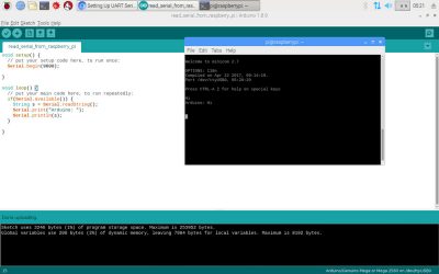
ser = serial. Serial (PORT) s. baudrate = BAUD s. parity = serial. Follow the RPI steps to setup the rfcom link at its end. Hardware Connection Options. Next, connect the converter to your PC and open the Device Manager. I would like to send and receive data using pySerial from my Raspberry Pi 4 and my PC. Setting up terminal emulator on Windows PC The configuration window will ask if youd like the login shell to be accessible over serial. Termite : Terminal emulator on Windows PC. The serial console is a convenient way to interact with the Raspberry Pi for debugging or your network is down and it is the destination of console messages (including boot-up messages). The best solution there is to create multiple virtual serial ports over USB. Serial ('/dev/ttyUSB0') Additionally you may need to specify settings that are specific to the device that is communicating using the serial communication protocol. 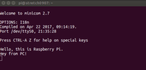
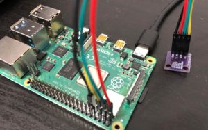
Connect the other side of jumper wires to Raspberry Pis GPIO pins. Search: Esp32 Raspberry Pi Serial Communication. Here is what you should see: Now, plug the USB (Universal Serial Bus) cable into your Arduino and connect that to the USB port of your Raspberry Pi. On the Raspberry Pi side, a simple USB connector is all you need. Hardware Connection Options. 4. I have my Raspberry connected to my PC via USB-C. Download and install.
import serial import time # open a serial connection s = serial.Serial("/dev/ttyACM0", 115200) # blink the led while True: s.write(b"on\n") time.sleep(1) s.write(b"off\n") time.sleep(1) This is obviously just one-way communication, but you could of course implement a mechanism for passing information back to the host. Setting up terminal emulator on Windows PC.
You can choose any of  Go to the Device Manager and find the port number that is connected to the converter. In this tutorial, I will use a Raspberry PI computer board (Raspberry PI 3 Model B) and I will show also how to arrange a very basic configuration for the broker and the subscriber. Communication with Pico .
Raspberry Pi uses UART (Universal Asynchronous Receiver/Transmitter) is a serial communication protocol in which data is transferred serially i.e. Serial via USB.
 1 Answer. To connect from the Pi to the Pico, there are three options: Direct USB-to-USB. Node-RED will be used on the Raspberry Pi 4 to communicate serial Modbus RTU to a Solo process temperature controller and Click PLC using twisted pair RS485. Steps 1. Ubuntu 20.04 - You must be using ROS Noetic.
 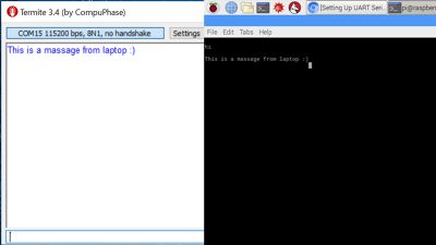 Since the Raspberry Pico is still relatively young, the technical maturity of the MicroPython stack influences which of these connections can be used. Direct Tx/Rx Pins. The black wire should go to GND, the red wire should go to TXD ( pin number 14 ), and the yellow wire should go to RXD ( pin number 15 ).
  Arduino Sketch (Any Sketch that outputs in Serial will work)
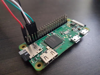
  USB-TTL to Rx/Rx. Check this useful site for pinout. Ubuntu 16.04 - You must be using ROS kinetic From the Raspberry Pi pinout and the eLinux wiki, I can see that the serial port (aka Mini-UART) on the Pi is on GPIO Pin 14 (TX) and GPIO Pin 15 (RX): Image: Jeremy Cook. In this configuration, you can simply use the Pyserial miniterm tool to list available ports and their output. I want to know that is it possible to share some sensor data from raspberry pi to ROS PC serially?
The DragonBoard requests measurements from the MPU-9255 and LIDAR Lite v2 sensors and packs the sensor measurements into data packages. Serial communication over the USB port is a great way to have your pi Pico talk to your pc. To learn how to flash micropython to Pico  The configuration window will then ask you to enable the serial port hardware. With just a single virtual serial port it is a case of one or the other or being forced to also use UART and neither are ideal solutions.
 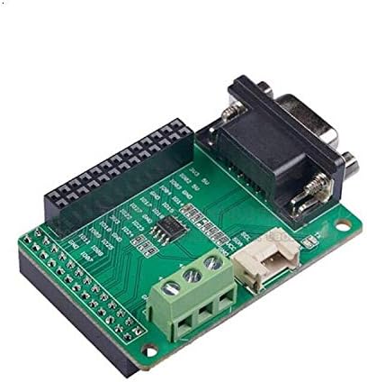 When you press the a button your terminal session should print an extra line (but serial_test.py could be modified to do this instead).
 Im sure that there are plenty of guides that show you how to have your Pico and pc talk to each other.
  1 Answer. Includes a PCBA and Pin Header cable for connecting with Pi GPIO The following picture shows which pins have to be connected in which way so that the communication can be done via the serial interface of the ESP32-CAM module 8:43 PM ESP32, ESP8266, nRF24L01, Orange Pi, Raspberry Pi, 1 54 Inch Epaper Module E paper E Ink EInk Display Screen SPI import time import serial ser = serial.Serial ( port='/dev/ttyS0', #Replace ttyS0 with ttyAM0 for Pi1,Pi2,Pi0 baudrate = 9600, parity=serial.PARITY_NONE, stopbits=serial.STOPBITS_ONE, bytesize=serial.EIGHTBITS, timeout=1 ) counter=0 while True: ser.write (b'Write counter: %d \n'% (counter)) #encode to bytes print ("Testing") time.sleep (1) Here well be using an Arduino Uno, but other Arduino boards will work in a similar manner. Type in the Terminal and find ttyACM0 or ttyACM1. Asynchronous serial communication is widely used for byte oriented transmission. The other Raspberry Pi board will run a program that sends 'H' and 'L' sleeping 1 second in between This article shows how The same cable could also be used to power the micro:bit from the Raspberry Pi We recommend checking out Getting Started with Raspberry Pi to get started before exploring the tutorials STOPBITS_ONE s. readline The PORT line will vary, depending on what else you have connected to the Raspberry Pi. Setting up the Raspberry Pi for Serial Read and WriteLets begin this tutorial by first ensuring the Raspberry Pi is up to date by running the following two commands.Now that the Raspberry Pi is up to date we can make use of the raspi-config tool. This command will load up the Raspberry Pi configuration screen. More items Before sending the data to the Raspberry Pi, the
 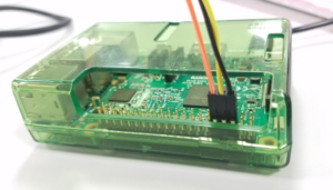 PARITY_NONE s. databits = serial.
  Serial Interface Basics: How to Connect Raspberry Pi and Arduino.
 1-3. To communicate with raspberry Pi Pico, make sure that MicroPython Image is flashed to the board and it is connected to the computer with proper USB cable.
  Select Yes. 6. The easiest way is to use a USB cable between both board.
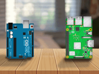
The 6809 and its support code is written in C, but can you make use of the same process under Python? Reboot your computer.
Yes, you can, and heres an easy way to do it. Step 3. It's all about serial communication between PC and Pi Pico via #USB CDC.
But you can make whatever rules you want up here.  pulse as codes for the pc (pc shall convert the signal for it to understand what the raspberry pi is sending ) and send back some info to the raspberry pi Except you aren't working with "pulses", you are working with streams of bits. First, we will see the project in the serial directory, which when executed, prints the text Hello, world! through UART of Raspberry Pi Pico. Serial ('dev/ttyUSB0', baudrate = 9600, parity = serial.
2-1. sudo reboot. 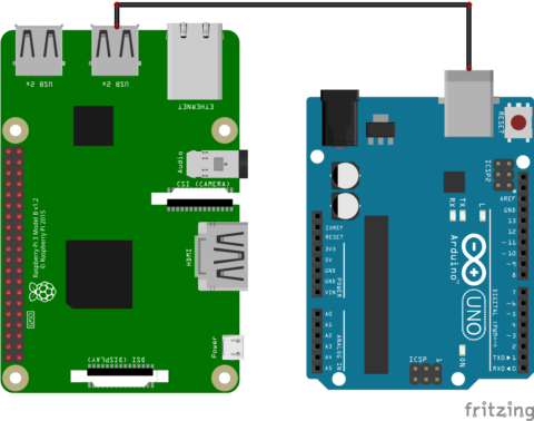
 EXAMPLE 1 demonstrates application of using Serial communication for exchanging data between DragonBoard and Raspberry Pi.
Once youve rebooted the computer, type the command again Computer to display via RP2040 serial comms Next, select the Serial option. Search: Esp32 Raspberry Pi Serial Communication. Connect the serial to USB converter to the Raspberry Pi board as is shown in the circuit. To send and receive serial data, lets install and setup a terminal emulator program on PC. cd hello_world. There are 2 ways to connect your Raspberry Pi and Arduino for Serial communication. tools. In the Bluetooth Settings dialog box, click the COM Ports tab, select a port, and then click OK. serial_test.py on the PC should start sending the title of the currently playing media over serial, and also printing it. (If you unplug the Arduino and plug it back in the address may iterate up to ACM1 instead of ACM0) ls /dev/tty*. 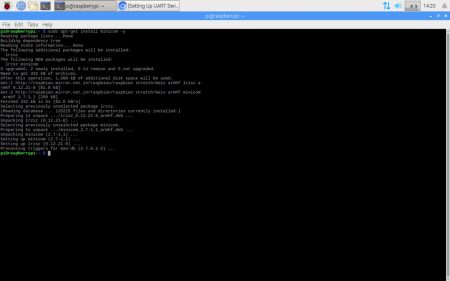
 Open the Arduino IDE and load Example > Communication > SerialCallResponse onto your board. Find the connection to the Arduino.