document.getElementById( "ak_js_1" ).setAttribute( "value", ( new Date() ).getTime() ); Im also interested in larger Stirling designs for the production of electricity from solar power. The Ringbom requires no mechanical linkage between the two chambers. Because it was so fragile, I decided the best way was to spin it in the lathe and slowly score it with a sharp-pointed tool. Stirling engines on small scales that hobbyists build them, tend to be fairly delicate in a balance between the the amount of power it produces, the weight and balance of the fly wheel and the friction throughout the entire system so there will undoubtedly be problems with your new engine, especially if this is the first one you built.  Barry Dunmans coffee table Stirling is a delight. These days electronic circuit-board components are soldered with a lead-free solder paste which consists of tiny solder balls in a ux. I have always wanted to build one. While that is curing, take the other aluminum sheet and find the center and drill a hole for the 1/16 ID beats pipe. Take the cardboard circle and drill a 1/16 inch hole (only through 1 layer of cardboard) in the center and use more JB weld to glue the 1/16 inch OD brass pipe in to the hole. I heated up the tube and cap, hoping the solder would melt inside and wick up into the joint. If I had to make it again, I would get a longer piece of metal, for sure. 15. Plus, well give you access to some great CNC reference materials including: Just enter your name and email address below: Your email address will not be published. Low Temperature Difference Stirling: Run a Stirling just by setting it on top of a steaming mug of coffee. Self-taught Im largely a self-taught model-engineer with a passion for making engines. After a while I tried icking the ywheel. I like the styling, Another ridiculously cool Bohm model! I still cant quite make out how the displacer end works. I faced and drilled then bored out the acrylic plastic using a boring bar to the correct size. A really novel Stirling design. 11. Then mark the point just over the displacer rod on the wire and again 1/8 inch on either side. Clear cylinder The next logical part was the clear cylinder which you need to make before the piston, so the piston can be honed down to be a perfect t for the bore. Put the pipe glued to the displacer from the bottom of the aluminum sheet, through the 1/16 inch ID pipe and out the top. Doing some research on the internet, I came across something called a stirling engine. Next project in the pipeline!!
Stirlings 1815 design used the following ratios: The purpose of making the heater chamber longer than the cooler was to maximize the temperature differential between the two. Reform the Z bend so that the top loop is at the same height as the suspended wire. Marbles are 12.5mm in diameter (half an inch), and so a 14mm test tube works well for a Test Tube Stirling. Get our latest blog posts delivered straight to your email inbox once a week for free. There are a few basic parts to the kind of stirling engine we are going to build. its tolerances aren't so tight, so that air can flow in the cylinder around the "piston" (displacer) which causes the displacer to move the air away from the heat source. Aquatap is a Ringbom Stirling by Roy Rice at Stirling South. Steele Stirling Engine Plans: A 4-cylinder design capable of claimed 40 watts. Looks like it took some waterjet or laser and CNC to make it. So the problem had to be in the sliding yoke. The outside shape can be a bit ddly to do but usually, a bit of milling and ling can produce a good looking conrod. The net result is that it is easier to make a small Stirling Engine than a big one. Other sources recommend a stroke that is 10% of the bore. I put a tiny amount on the parts that need to be soldered together and remove any excess. Measure the distance between the loop on the piston to the suspended wire. The rest of the site is also quite fun! What was required was a nice low-friction, gas-tight t between the rod and sleeve. It is impossible to completely seal off the piston or the displacer shaft (otherwise there would be too much friction) but make sure that if you were to submerge it under water, there are no leaks. People who live in colder areas may see better performance out of one of these engines where as people in warmer regions like me may struggle to keep the engine running. The engine I built has two cylinders. These all came from sites in the links above. LTD Striling Plans: Plans for a relatively easy to build LTD. Free Piston Stirling from Japanthatll run on a cup of coffee. Make sure that no air can escape the engine. On the wire, mark out the point where the center of the the piston is, then mark 1/8 inch on both sides. Again the best method was to run the tube on a split mandrel so the pipe ID was running true. He and Dr. Ivo Kolin at the University of Zagreb back in the 80's had a friendly competition to see who could build a Stirling engine that ran on the smallest difference in temperature. The heated air expands and pushes the piston out, turning the wheel, 3. length of displacer = 2/3L and stroke = 1/3L. This is my first instrucable so please feel free to leave some constructive criticism and if you really like it then make sure to vote! The trick to silver soldering is that you need only a tiny amount. First, they use gas at high pressure. Now that we have all our pieces, we can put it together. Make a low-pressure, hot air engineBy Ross Purdy. Nice scale of Stirling. 3. 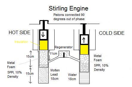 Stirling stopped pursuing the idea without knowing how it would be used today. You can control the temperature very well and not discolour the workpiece. Minimize dead volume. Join 100,000+ CNC'ers! I put the material prep in 1 step because otherwise there would be hundreds of steps. The last part to make was the large round aluminium heatsink. Here is themain Stirling page. A neat illustration of the engine and the story behind it is here: http://www.animatedengines.com/ltdstirling.html. There was nothing to hold in the chuck; so a bit of extra material would have made the task so much easier.As it was, I had to make another split mandrel to try and hold it but it was very difcult to get any drive to it while cutting those ns. To get the brackets soldered nice and square I just relied in the end on the re bricks to prop the work up square while I soldered. Second, wherever possible, minimize the mass (weight) of the moving parts. Mix up some of that JB Weld and glue one of the aluminum plates to the bottom of the strip of plastic bottle. In the 90's, NASA was experimenting with putting a stirling engine into a truck. 5. I began the construction of this engine with the two fabricated brass brackets for the drive cylinder and displacer cylinder, not easy as both were fabricated from several brass extrusions silver-soldered together. This site has a nice one and a movie of it running. These pieces of wood are there to support the aluminum because it is a little too thin to support all the weight and handle the stresses the engine will put on it. It was especially true for this one because I had had no previous experience in making such an engine. I thought it must have been in the rod and sleeve although that also seemed ne. Not sure about other sizes. Roy UKs Stirlings: Several to choose from made from simple materials. Running Now all the parts were together and everything looked about right so it was time for the big test: would it run as an engine?I half-lled the burner with meths and lit it. The piston was a little tight at one point in the bore as plastic isnt the most stable material to machine. Coffee Table Stirling Engines: Nice collection of photos. My second attempt with a bit more heat nally did the job. This pushes the gas down the tube while the crank pulls the displacer piston back to the cold end of the displacer cylinder (E), shifting the gas from there to the hot end (A). Heat is applied at one end to the displacer cylinder (A). Cylinder head, air port The drive cylinder head and air port were straightforward parts to machine and were soft-soldered together using my heat-gun method. I then painted the completed brackets with a spray of grey etch-primer to key into the metal (otherwise the paint chips off easily), followed by a spray of car primer/ller which works wonders in lling slight imperfections. To do this, I had to make a dummy piston the right size for the bore that screwed onto the 3 mm piston rod. The Shedmagazineis eclectic, informed, and always fascinating. Before you put the cam shaft back into the holder, slide the connectors on to their respective cams and tighten up the loops so that they can't come out, then put the shaft back into the holes on the popsicle sticks. You gotta love the Steampunk + Raygun motif. Since the engine runs on the rapid heating and cooling of a working fluid, it is important that there is a high temperature gradient. When it hits the melting point, it will ow every-where (even where you dont want it). Yoke, heatsink Only two more components needed to be fabricated to complete the engine, the yoke and heatsink . "So, what the heck is a stirling engine?" Acrylic (or Perspex) will polish up really quickly and easily with a bit of Brasso on a rag. The cycle repeats as long as the cold end of the displacer remains cooler than the hot end. Share it with us! Cut a 8 inch piece of wire and straighten it out as much as you can then put it through the holes in the popsicle sticks. Barry Dunman: His coffee table Stirling is a delight. I replaced it with a 3 mm silver steel rod. The easyo ux is a liquid paste and you brush a small amount along the joint. Here isa gallery of pix building one. However, according to a quick look at Wikipedia, "A Stirling engine is a closed-cycle regenerative heat engine with a permanently gaseous working fluid". Jon Bondy: Has built several model Stirlings, has a Stirling design program on the site, and keeps octopus and cuttlefish as pets. Over time, the heatsink gets hot and the engine slows but by this time the burner is out of meths anyway. The counterweight was easily done by milling away each side while the crank disc was held in a machine vice. Very nice, and the demonstration of the concept is excellent.I built the two candle power Stirling engine. The engine runs at about 600 RPM with a good differential between the hot and cold ends of the displacer tube. 6. How do you go wrong with that? I made the tube a good t in the ange so that it would hold itself square while I soldered it.Now the displacer assembly needed to be tted to the bracket with the bore in the centre of the piston-sleeve. I wasnt happy with the look so I made a whole new piece from an offcut of plastic. Aimed at those with a few tools and perhaps a few clues: this is the magazine for real sheddies. The stirling engine was invented by a fellow by the name of Robert Stirling. After this all cures, touch up the seal with a little more JB Weld, we want this to be air tight. When the piston was a tight t in the bore I began polishing the outside of it with 1000 grit wet & dry paper wrapped around a at bar. The ywheel is an easy machining job. The displacer moves air inside the engine to heat it up or cool it off. Our Big List of over 200 CNC Tips and Techniques. also since it works because of the temperature gradient, you could cool the top side to get even better performance out of it. At the same time, the crankshaft moves a displacer piston (D) inside the displacer cylinder (A) towards the hot end to displace the hot gas to the cold end of the tube (E). This ratio is much larger for Low Temperature Differential Stirlings. A threaded aluminium insert was Loctited into the tube to complete the displacer piston. 12. Wait, I thought, the bolt isnt round. Test Tube Stirling: Test Tube Stirlings may be the simplest way to play with a Stirling. With hard soldering, I dont like seeing the nice shiny parts Ive just made oxidizing badly as they are heated to high temperatures. Alphonse Vassalo: Many finely crafted Stirling models including a 4-cylinder. Cut another piece of wire about 4 inches in length and put a loop in both ends and bend a "Z" shape into the wire to allow for some adjustments. The next day after everything has cured, take the aluminum sheet with the pipe glued to it and mark a spot between the center and the edge of the circle and cut out a 3/4 inch hole. Made by a company called JAXA. The gas cools there and contracts, sucking the drive piston back to the top. It turned out to be very easy to do. It looked like it had been glued together from three sheets which made it have two internal rings. Once it had cooled down, I started to go over the engine trying to nd out why it wouldnt run. The cylinder needs to be held from the internal hole and the outside turned to the required dimensions. First, I sand with some 800 grit wet & dry then move up to 1000 or 1200 and then nish with the Brasso to get it back to crystal-clear again. This configuration of engine was looked at, among other uses, as a CPU cooler for computers.