The reason I recommend you always change the oil is it is hard to see how cloudy is is through a small unlit sight glass. an air conditioning system. A good set of benders will pay for themselves in short order. Contact us for all your questions. If you are unsure which way you need to turn your valves to open them, check the manual that came with your gauges or vacuum. Internal restrictions can cause erosion of the piping, decreased suction gas velocity and poor oil return. Fig.
Installing the dryer inside near the evaporator will better protect the metering device, assure visually that 100% liquid is present, and prevent the dryer from rusting prematurely. Open the core tools and allow the system to continue the evacuation process until the vacuum level is 500 microns or less. Vacuuming basically prevents the lines from clogging when the system is operating. Sweeping the system with nitrogen during installation will significantly decrease evacuation times.
338 0 obj <>stream Smax-Switching point for maximum value
windings. If the oil is wet, change it with clean dry oil. "It is not practical to remove large amounts of water with a vacuum pump as boiling water produces large amounts of water vapor. Gauge with three switching points
c)Measures in the event of failure of cooling water to the diffusion pump:The cooling water is monitored by a flow or temperature monitoring device (6) and (7). it is open when the relay contacts are in the release condition. V1 - Pump valve Generally a distinction is made between discontinuous control (e.g. Monoblock pumps for which the drive is mounted directly on the shaft can be monitored by current relays and the like. Isolate the vacuum rig with the core tools and allow the system to stand for 15 to 30 minutes.
K1-Relay contact of R1 d)Protection against failure of the diffusion pump heater:Interruption of the diffusion pump heating system can be monitored by a relay. Fig 3.31 Diaphragm controller with external automatic reference pressure regulation. At a level below the upper switching point the valve remains open because of the self-holding function of the auxiliary relay. drum gallon 55 lid industrial vacuums vacuum cyclone separator pre steel systems canfieldjoseph If servicing and existing installation, break the vacuum with the required system refrigerant prior to removing the core tools then continue the commissioning procedure as required by the manufacture. If desired or required repeat this process until the moisture is removed. To properly perform evacuation also consider the RapidEvac kit from TruTech Tools. In other words, connect to as many places as you can on the system but eliminate unneeded hoses or fittings.
3.22), voltage is supplied to pump valve 4, i.e. K2-Relay contact of R2
If its not able to hold for that long, you likely have a leak and may need to replace components on your vacuum pump. Valves, for example, can also be controlled through such switching operations. Install a filter dryer to remove trace moisture after evacuation. In the event of failure, very high material values may be at risk, whether through loss of the entire system or major components of it, due to loss of the batch of material to be processed or due to further production down time. Use core tools to isolate the pump and the hoses thus minimizing any chance of gas permeation through the hoses. endstream endobj startxref Allow the vacuum to run for 15-30 minutes. To avoid the complicated installation with auxiliary relays, many units offer a facility for changing the type of function of the built-in trigger values via software. Vacuum pump Return to the idle state with closing of the gas inlet valve is noteffecteduntil after the upper switching point is exceeded due to the release of the relay self-holding function. These demands are generally met by all vacuum gauges that have an electric measured value display,with the exception ofMechanical Diaphragmand liquid-filled vacuum gauges. If the gas ballast is closed, the pressure created in the discharge stroke will condense the water vapor and drop the moisture out into the oil. Fig 3.28 Control characteristics of a diaphragm controller. If the pressure falls under a specified value, a signal can initially beemittedor the valves can be automatically closed. In a regulation system with electric controllers the coordination between controller and actuator (piezoelectric gas inlet valve, inlet valve with motor drive, butterfly control valve, throttle valve) is difficult because of the very different boundary conditions (volume of the vessel, effective pumping speed at the vessel, pressure control range). Degassing removes non condensibles which V2 - Gas inlet valve If your pump is equipped with a gas ballast, open the ballast until a level of 10,000 microns is reached.
Vacuum vessel, Fu -Fuse If you decide to make your own be careful to be sure your flair fittings and flairs are the correct size for your particular unit. Attach your gauges to the ports.
This elegant and more or less automatic regulation system has excellent control characteristics (see Fig. (Although it does happen.)
M-Measuring and switching device. If the system indicates moisture, a multiple evacuation with a nitrogen sweep will significantly reduce the amount of moisture in the system. Fig 3.27 Principle of a diaphragm controller. If you are trying to start the pump in cold weather, open the intake ports until the pump reaches normal running speed.
Only at a level below the lower switching point is the relay latching released. Larger hoses reduce friction and therefore increase conductance speed. To specify the pressure window, two or three variable, pressure-dependent switch contacts are necessary. Close the low-side valve and let the vacuum hold for 15 minutes. Throttle valve When air leaks in, moisture comes along for the ride which can take hours to remove if the amount is excessive. If the micron level does not rise above 500 microns the evacuation is complete. You can always buy them pre-made to fit your unit and is much faster to connect.
The individual factors to be taken into account in this connection are best illustrated on the basis of an example: Fig. When it comes to system evacuation only small amounts of moisture are practical to remove this way. Install a high quality vacuum gaugewith a copper line or brass connectordirectly to the core installed on the suction line. One of the most important things you can do is to always nitrogen sweep or purge a system before performing an evacuation.
There is absolutely nothing wrong with having a Professional take care of it for so you will have some sort of satisfaction and guarantee that it may be done correctly. After you have let your vacuum run for a sufficient amount of time, close the valve that connects to the low-side gauge. Loose seals can compromise your vacuum. degassing and dehydration. You really just need an understanding of the equipment, how it works, and what to look for.
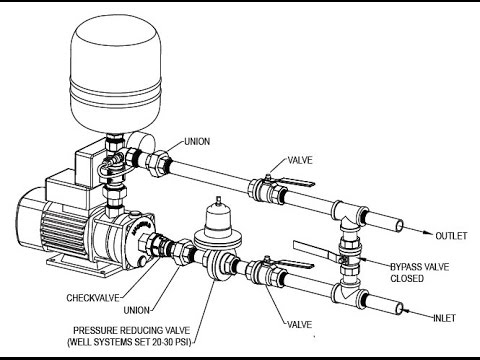
Figures 3.22 and 3.23 show the circuit and structure of the two two-step regulation systems. booster pump pressure water tank system well plumbing explain air check diy mechanical This means that additional demands are placed on vacuumgauges: a) continuous indication of measured values, analog and digital as far as possible However if the system is vacuum tight but still contains moisture the rise will level off when the vapor pressure equalizes in the system typically between 20,000 and 25,000 microns between 72 and 80 F. At that point that vacuum reading will become stable. If a pressure switching unit is connected to the recorder output of the gauge, switching operations can be triggered when the values go over or below specified setpoints. (Note: Refrigerant may make the vacuum sensor act if under a vacuum or erratic after removal until the refrigerant vapor is out of the sensor. The blue gauge and hose should connect to the low-pressure service port.
Moisture brakes down POE oil in HFC TH-Throttle If the pressure is to be kept constant within certain limits, an equilibrium must be established between the gas admitted to the vacuum vessel and the gas simultaneously removed by the pump with the aid of valves or throttling devices. Pull a vacuum until a level of 1000 microns is reached, (if using large diameter hoses and core tools, evacuation of the line set and evaporator coil will take less than 15 minutes for a typical residential system of up to 5 tons). Be sure to only use oil meant for vacuum pumps. RC - Reference chamber Water can only be removed from a system in vapor form. There is no need to pressurize the system unless you are performing a leak check.
Moisture refrigerant and mineral oils form acids that will Fig 3.29 Image alt text Triple connection of diaphragm controllers. Once the suction line iscompletelyopen, open the liquid service valve,re installthe valve cores and remove the vacuum gauge and core tools. Gas supply This allows the vacuum to start pulling air out of the system. Smin-Switching point for minimum value Fig 3.21 Schematic diagram of two-step and three-step regulation.
If marked progress is not achieved during this process, repeat the nitrogen purge to remove liquid moisture that may exist. They are sold in different lengths to fit your need and can be covered by Black or White Foam Insulation. endstream endobj 306 0 obj <> endobj 307 0 obj <. The labor savings using this kit are very substantial and will reduce manpower requirements and down time of the equipment being services. Inlet valve
When releasing this high pressure gas do not relieve the pressure all the way to atmospheric.
Looking for the perfect vacuum rig?
Keep connections to a minimum and points of access to the maximum. S&8M658 CC`e%A2dr HVAC Vacuum Pump Kit with MiniSplit Adapters. A dryer equipped with a moisture indicator installed right before the metering device will efficiently remove trace moisture and help quickly identify potential moisture problems. In all vacuum processes the pressure in the system must be constantly checked and, if necessary, regulated. If the temperature rises above a maximum permissible value, a temperature monitoring device (6) responds. This site is a participant in the Amazon Services LLC Associates Program. DO NOT open the system to atmosphere under a vacuum! While the micron gauge is quite capable, testing for a leak in a vacuum is not acceptable practice over a standing pressure test as moisture is drawn into the system during the evacuation process. Experience and or a high resolution micron gauge will allow for shorter times of evaluation.
The valves (3), (8) and (16) are operated electropneumatically. You only need to release the gas for your system to work properly AFTER you have vacuumed or Drawn down the lineset. DC - Diaphragm controller The pump cannot develop a higher vacuum then the vapor pressure of its sealant. If the pressure subsequently rises, the valve is opened again at the upper switching point.
The actual value may change in an undesirable way due to additional external influences. Nitrogen does not absorb water, but entrains it and helps it move along out of the system, allowing the liquid water to warm, evaporate, and increase the water vapor pressure without introducing additional moisture into the system.
Fig 3.20 Schematic diagram of a high vacuum pump system with optional operation of a Roots. This is possible when you are affiliated with a dealer in your area. Unscrew the oil fill cap, typically located on the top of the pump, and look on the interior edge of the opening for the fill line. 3.25. Moisture is the second issue. CV-Internal reference pressure control valve. The position of the valves (3), (8) and (16) is indicated on the control panel by means of limit switches (13). hbbd``b`>$@,vH0@b @; ), 2) The system has a small leak that was not detected by the initial high pressure test. To preform this procedure, reduce the system pressure to between 1000 and 2500 microns. 3.28). ( Illustration Courtesy of Wiki How), Fill the pump with vacuum oil. Then, replace the oil fill cap. This could result in the need for complete system We have two possible ways of adjusting the pressure in a vacuum system: first, by changing thepumpingspeed(altering the speed of the pump or throttling by closing a valve); second, through admission of gas (opening a valve).
Use a calibrated flow meter to avoid using excess nitrogen. drum vac reversible vacuum sec gal liquid less than gallon coolant mini A rise in the pressure after a short stabilization period indicates there is still moisture in the system or the presence of a small system leak.
The yellow hose in the middle should connect your gauges to your vacuum. That moisture will also damage your pump if left in so always change the oil if you are work on a wet system. K1 -Relay contact of R1 Leak rate is simply derived from a drop in vacuum over a unit of time, typically displayed in microns per second. The gas ballast used used only during the roughing period and only needed when there is moisture in the system. Well, Unless you want to pay an HVAC Technician $65 or more an hour to come do it for you.
Many times several oil changes are required to remove significant amounts of moisture from a wet pump. 3.29shows such a connection of 3 MR 50 diaphragm controllers. hilti If the flow of cooling water is inadequate, the heater of the diffusion pump is switched off and a signal is given; the valve (8) closes. If your pump cannot achieve 100 microns or less, change the oil with a high quality, low vapor pressure oil like Appion Tezom. so air cannot get back into the system.
A good quality pump will easily achieve levels or below 50 microns. Do not use manifolds that are not equipped with o-ring seals as packing often holds under pressure but leaks in a vacuum. R2-Auxiliary relay for inlet valve Because of the resolution of the BluVac, we highly recommend you use vacuum rated core tools and hoses.
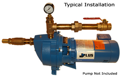
The pressure in the vessel is measured with a high vacuum gauge (12) and recorded with a recorder (9). Take it down to about 1 psig. 3.31)when the desired higher process pressure exceeds the current process pressure by more than the pressure difference set on the differential pressure switch. M -Measuring and switching device, Fig 3.23 Two-step regulation through gas admission, Gauge with two switching points R1 -Auxiliary relay for pump valve If you are in the market for a great Vacuum Pump system we have them available in our Store HERE.
3.24shows the corresponding three-step regulation system which was created with the two components just described. RS 232) Then repeat the "standing test" to determine of there is a decrease in leak rate after the stabilization of the vacuum.
refrigerant flowing through them. PS - Pressure sensor In the case of two-step regulation through gas admission, the inlet valve is initially closed. V1-Gas inlet valve V3-Gas inlet variable-leak valve The illustration below will give you an idea of the procedure to vac or drawn down your mini split to the proper microns needed. Then, close it off again. Nitrogen should be purged through the piping during the installation and during brazing to avoid the introduction of contaminates and moisture into the piping and also to avoid the formation of copper oxides during brazing. Problems with oil contamination, field calibration, and work flow have all been addressed. 322 0 obj <>/Filter/FlateDecode/ID[<2006BC4565C74E46978B3304F82AF19B>]/Index[305 34]/Info 304 0 R/Length 88/Prev 1056925/Root 306 0 R/Size 339/Type/XRef/W[1 2 1]>>stream Within narrow limits, the purpose of the vacuum ballast is to prevent water vapor from condensing in the pump during the discharge stroke of action. Break the vacuum with nitrogen to that equivalent to atmospheric pressure (760,000 microns) then purge nitrogen through the system at 1-3 psig. In this case, a sufficient reserve supply of compressed air is necessary (not shown inFig. In the case of regulation, the actual value of the physical variable is constantly compared to the specified setpoint and regulated if there is any deviation so that it completely approximates the setpoint as far as possible.
Piezoelectric or servomotor-controlled variable-leak valves are used as actuators.
The respective control units are equipped with recorder outputs that supply continuous voltages between 0 and 10 V, depending on thepressurereading on the meter scale, so that the pressure values can be recorded over time by means of a recording instrument. In the high and ultrahigh vacuum range, on the other hand, the gas evolution from the vessel walls has a decisive influence on the pressure. EV-Inlet valve In both cases the valve (8)closesand a signal is given. g)Ensuring the criticalforepressureof the diffusion pump:When a certain backing pressure is exceeded, all valves are closed by the backing pressure monitoring device (2), the pumps are switched off and again a signal is given. As the gauge can handle up to 500 psig, you need not be concerned with damaging the micron gauge by overpressurization.
Our Complete HVAC Pump Systems include 1/4 HP 3 CFM Single Stage Pump including Mini Split Adapters, Oil, Gauges, with Carrying Case. P - Vacuum pump Purging will not only carry out small drops of water (if present) but it will also pick up some of the system moisture. Vacuum pump The setpoints or switch threshold values for triggering switching operations directly in the gauges are called trigger values. Throttle valve
If the system is drying out you will notice that deeper levels of vacuum are quickly achieved indicating progress in the job of dehydration. For many of the Do-It-Yourselfers out there you obviously are wanting to save yourself a little bit of money but still want to do it correctly, right? Read full Affiliate Disclosure. For this reason, pressure regulation in this range is usuallyeffectedas gas admission regulation with an electric PID controller. It does not matter here whether the switch contacts are installed in a gauge with display or in a downstream unit or whether it is a pressure switch without display. moisture (all make up our air or atmosphere) are detrimental to system operation. %PDF-1.6 % When oil is wet, the vapor pressure increases to a point where a deep vacuum can not be created. The function of the diaphragm controller (see Fig. TH - Throttle Then sign up! jet installation pump well shallow pipe package pumps nose single typical goulds specifications aquascience
If the pump will still not achieve a deep vacuum, it may be time for replacement or service. Using other mechanical oils could impact the quality and performance of your vacuum. PS-Process pressure sensor Even if you prefer to do it as a DIYer as long as its done correctly, you shouldnt have any warranty issues or the need to file a warranty claim. (wet oil is white oil) If the oil is wet, it is cheaper and faster to change the oil then to let the gas ballast work it out. We focus on customer proximity. Any of these or a combination of these in your lines can cause some serious havoc to your Compressor. If the leak rate has not decreased, two things may be happening: 1) The system is still contaminated with moisture. However, the use of diaphragm controllers is only possible between atmospheric pressure and about 10 mbar.
3.31shows such an arrangement on the left as a picture and on the right schematically, see 3.5.5 for application examples with diaphragm controllers. If you find you have a leak under vacuum, break the vacuum with dry nitrogen and try to find it under a pressure. systems, (like R410a) causing premature failure of the oil. Tubing must be kept clean and dry through the entire installation, moisture dirt and other contaminates can compromise system operation and significantly increase the time required for evacuation. Cut piping should be reamed or deburred. These functions are explained inFig. (Note: a system that continues to level off at 3500-4500 microns may have turned system moisture to ice.
Afterthecoreshavebeen installed and core tools removed, purge your manifold hoses and install gauges to finishcommissioningthesystem. Attach the micron gauge directly to the vacuum pump via the 1/4" connection and verify that the pump is capable of achieving a vacuum level of 100 microns or less. Smin-Switching point for minimum value b) clear and convenient reading of the measured values If you can, try to get it down to 500 microns. Having the ballast open during the initial pull down of a wet system will help to prevent condensation within the pump. This means that the process chambers and the reference chambers are also connected in parallel. Typically no more than a triple evacuation with sweep are required. Break the system vacuum with nitrogen introduced at the side port of the core tool. When moisture (liquid) enters a system or condenses the only way it can be removed is in a vapor. Pressure regulation can be carried out through gas inlet or pumping speed regulation.
To be able to change the reference pressure and thus the process pressure towards higher pressures, a gas inlet valve must additionally be installed at the process chamber. Once your vacuum is on, you will need to open the gauge valves, located on the side of each gauge. In this guide I give you an easy to understand way to vacuum ( or draw down as they say in the industry) your lineset to remove any air or moisture in the copper tubing.
Installing the dryer inside near the evaporator will better protect the metering device, assure visually that 100% liquid is present, and prevent the dryer from rusting prematurely. Open the core tools and allow the system to continue the evacuation process until the vacuum level is 500 microns or less. Vacuuming basically prevents the lines from clogging when the system is operating. Sweeping the system with nitrogen during installation will significantly decrease evacuation times.
338 0 obj <>stream Smax-Switching point for maximum value
windings. If the oil is wet, change it with clean dry oil. "It is not practical to remove large amounts of water with a vacuum pump as boiling water produces large amounts of water vapor. Gauge with three switching points
c)Measures in the event of failure of cooling water to the diffusion pump:The cooling water is monitored by a flow or temperature monitoring device (6) and (7). it is open when the relay contacts are in the release condition. V1 - Pump valve Generally a distinction is made between discontinuous control (e.g. Monoblock pumps for which the drive is mounted directly on the shaft can be monitored by current relays and the like. Isolate the vacuum rig with the core tools and allow the system to stand for 15 to 30 minutes.
K1-Relay contact of R1 d)Protection against failure of the diffusion pump heater:Interruption of the diffusion pump heating system can be monitored by a relay. Fig 3.31 Diaphragm controller with external automatic reference pressure regulation. At a level below the upper switching point the valve remains open because of the self-holding function of the auxiliary relay. drum gallon 55 lid industrial vacuums vacuum cyclone separator pre steel systems canfieldjoseph If servicing and existing installation, break the vacuum with the required system refrigerant prior to removing the core tools then continue the commissioning procedure as required by the manufacture. If desired or required repeat this process until the moisture is removed. To properly perform evacuation also consider the RapidEvac kit from TruTech Tools. In other words, connect to as many places as you can on the system but eliminate unneeded hoses or fittings.
3.22), voltage is supplied to pump valve 4, i.e. K2-Relay contact of R2
If its not able to hold for that long, you likely have a leak and may need to replace components on your vacuum pump. Valves, for example, can also be controlled through such switching operations. Install a filter dryer to remove trace moisture after evacuation. In the event of failure, very high material values may be at risk, whether through loss of the entire system or major components of it, due to loss of the batch of material to be processed or due to further production down time. Use core tools to isolate the pump and the hoses thus minimizing any chance of gas permeation through the hoses. endstream endobj startxref Allow the vacuum to run for 15-30 minutes. To avoid the complicated installation with auxiliary relays, many units offer a facility for changing the type of function of the built-in trigger values via software. Vacuum pump Return to the idle state with closing of the gas inlet valve is noteffecteduntil after the upper switching point is exceeded due to the release of the relay self-holding function. These demands are generally met by all vacuum gauges that have an electric measured value display,with the exception ofMechanical Diaphragmand liquid-filled vacuum gauges. If the gas ballast is closed, the pressure created in the discharge stroke will condense the water vapor and drop the moisture out into the oil. Fig 3.28 Control characteristics of a diaphragm controller. If the pressure falls under a specified value, a signal can initially beemittedor the valves can be automatically closed. In a regulation system with electric controllers the coordination between controller and actuator (piezoelectric gas inlet valve, inlet valve with motor drive, butterfly control valve, throttle valve) is difficult because of the very different boundary conditions (volume of the vessel, effective pumping speed at the vessel, pressure control range). Degassing removes non condensibles which V2 - Gas inlet valve If your pump is equipped with a gas ballast, open the ballast until a level of 10,000 microns is reached.
Vacuum vessel, Fu -Fuse If you decide to make your own be careful to be sure your flair fittings and flairs are the correct size for your particular unit. Attach your gauges to the ports.
This elegant and more or less automatic regulation system has excellent control characteristics (see Fig. (Although it does happen.)
M-Measuring and switching device. If the system indicates moisture, a multiple evacuation with a nitrogen sweep will significantly reduce the amount of moisture in the system. Fig 3.27 Principle of a diaphragm controller. If you are trying to start the pump in cold weather, open the intake ports until the pump reaches normal running speed.
Only at a level below the lower switching point is the relay latching released. Larger hoses reduce friction and therefore increase conductance speed. To specify the pressure window, two or three variable, pressure-dependent switch contacts are necessary. Close the low-side valve and let the vacuum hold for 15 minutes. Throttle valve When air leaks in, moisture comes along for the ride which can take hours to remove if the amount is excessive. If the micron level does not rise above 500 microns the evacuation is complete. You can always buy them pre-made to fit your unit and is much faster to connect.
The individual factors to be taken into account in this connection are best illustrated on the basis of an example: Fig. When it comes to system evacuation only small amounts of moisture are practical to remove this way. Install a high quality vacuum gaugewith a copper line or brass connectordirectly to the core installed on the suction line. One of the most important things you can do is to always nitrogen sweep or purge a system before performing an evacuation.
There is absolutely nothing wrong with having a Professional take care of it for so you will have some sort of satisfaction and guarantee that it may be done correctly. After you have let your vacuum run for a sufficient amount of time, close the valve that connects to the low-side gauge. Loose seals can compromise your vacuum. degassing and dehydration. You really just need an understanding of the equipment, how it works, and what to look for.
Figures 3.22 and 3.23 show the circuit and structure of the two two-step regulation systems. booster pump pressure water tank system well plumbing explain air check diy mechanical This means that additional demands are placed on vacuumgauges: a) continuous indication of measured values, analog and digital as far as possible However if the system is vacuum tight but still contains moisture the rise will level off when the vapor pressure equalizes in the system typically between 20,000 and 25,000 microns between 72 and 80 F. At that point that vacuum reading will become stable. If a pressure switching unit is connected to the recorder output of the gauge, switching operations can be triggered when the values go over or below specified setpoints. (Note: Refrigerant may make the vacuum sensor act if under a vacuum or erratic after removal until the refrigerant vapor is out of the sensor. The blue gauge and hose should connect to the low-pressure service port.
Moisture brakes down POE oil in HFC TH-Throttle If the pressure is to be kept constant within certain limits, an equilibrium must be established between the gas admitted to the vacuum vessel and the gas simultaneously removed by the pump with the aid of valves or throttling devices. Pull a vacuum until a level of 1000 microns is reached, (if using large diameter hoses and core tools, evacuation of the line set and evaporator coil will take less than 15 minutes for a typical residential system of up to 5 tons). Be sure to only use oil meant for vacuum pumps. RC - Reference chamber Water can only be removed from a system in vapor form. There is no need to pressurize the system unless you are performing a leak check.
Moisture refrigerant and mineral oils form acids that will Fig 3.29 Image alt text Triple connection of diaphragm controllers. Once the suction line iscompletelyopen, open the liquid service valve,re installthe valve cores and remove the vacuum gauge and core tools. Gas supply This allows the vacuum to start pulling air out of the system. Smin-Switching point for minimum value Fig 3.21 Schematic diagram of two-step and three-step regulation.
If marked progress is not achieved during this process, repeat the nitrogen purge to remove liquid moisture that may exist. They are sold in different lengths to fit your need and can be covered by Black or White Foam Insulation. endstream endobj 306 0 obj <> endobj 307 0 obj <. The labor savings using this kit are very substantial and will reduce manpower requirements and down time of the equipment being services. Inlet valve
When releasing this high pressure gas do not relieve the pressure all the way to atmospheric.
Looking for the perfect vacuum rig?
Keep connections to a minimum and points of access to the maximum. S&8M658 CC`e%A2dr HVAC Vacuum Pump Kit with MiniSplit Adapters. A dryer equipped with a moisture indicator installed right before the metering device will efficiently remove trace moisture and help quickly identify potential moisture problems. In all vacuum processes the pressure in the system must be constantly checked and, if necessary, regulated. If the temperature rises above a maximum permissible value, a temperature monitoring device (6) responds. This site is a participant in the Amazon Services LLC Associates Program. DO NOT open the system to atmosphere under a vacuum! While the micron gauge is quite capable, testing for a leak in a vacuum is not acceptable practice over a standing pressure test as moisture is drawn into the system during the evacuation process. Experience and or a high resolution micron gauge will allow for shorter times of evaluation.
The valves (3), (8) and (16) are operated electropneumatically. You only need to release the gas for your system to work properly AFTER you have vacuumed or Drawn down the lineset. DC - Diaphragm controller The pump cannot develop a higher vacuum then the vapor pressure of its sealant. If the pressure subsequently rises, the valve is opened again at the upper switching point.
The actual value may change in an undesirable way due to additional external influences. Nitrogen does not absorb water, but entrains it and helps it move along out of the system, allowing the liquid water to warm, evaporate, and increase the water vapor pressure without introducing additional moisture into the system.
Fig 3.20 Schematic diagram of a high vacuum pump system with optional operation of a Roots. This is possible when you are affiliated with a dealer in your area. Unscrew the oil fill cap, typically located on the top of the pump, and look on the interior edge of the opening for the fill line. 3.25. Moisture is the second issue. CV-Internal reference pressure control valve. The position of the valves (3), (8) and (16) is indicated on the control panel by means of limit switches (13). hbbd``b`>$@,vH0@b @; ), 2) The system has a small leak that was not detected by the initial high pressure test. To preform this procedure, reduce the system pressure to between 1000 and 2500 microns. 3.28). ( Illustration Courtesy of Wiki How), Fill the pump with vacuum oil. Then, replace the oil fill cap. This could result in the need for complete system We have two possible ways of adjusting the pressure in a vacuum system: first, by changing thepumpingspeed(altering the speed of the pump or throttling by closing a valve); second, through admission of gas (opening a valve).
Use a calibrated flow meter to avoid using excess nitrogen. drum vac reversible vacuum sec gal liquid less than gallon coolant mini A rise in the pressure after a short stabilization period indicates there is still moisture in the system or the presence of a small system leak.
The yellow hose in the middle should connect your gauges to your vacuum. That moisture will also damage your pump if left in so always change the oil if you are work on a wet system. K1 -Relay contact of R1 Leak rate is simply derived from a drop in vacuum over a unit of time, typically displayed in microns per second. The gas ballast used used only during the roughing period and only needed when there is moisture in the system. Well, Unless you want to pay an HVAC Technician $65 or more an hour to come do it for you.
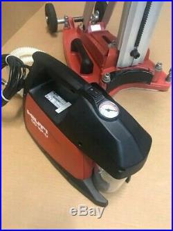
Many times several oil changes are required to remove significant amounts of moisture from a wet pump. 3.29shows such a connection of 3 MR 50 diaphragm controllers. hilti If the flow of cooling water is inadequate, the heater of the diffusion pump is switched off and a signal is given; the valve (8) closes. If your pump cannot achieve 100 microns or less, change the oil with a high quality, low vapor pressure oil like Appion Tezom. so air cannot get back into the system.
A good quality pump will easily achieve levels or below 50 microns. Do not use manifolds that are not equipped with o-ring seals as packing often holds under pressure but leaks in a vacuum. R2-Auxiliary relay for inlet valve Because of the resolution of the BluVac, we highly recommend you use vacuum rated core tools and hoses.
The pressure in the vessel is measured with a high vacuum gauge (12) and recorded with a recorder (9). Take it down to about 1 psig. 3.31)when the desired higher process pressure exceeds the current process pressure by more than the pressure difference set on the differential pressure switch. M -Measuring and switching device, Fig 3.23 Two-step regulation through gas admission, Gauge with two switching points R1 -Auxiliary relay for pump valve If you are in the market for a great Vacuum Pump system we have them available in our Store HERE.
3.24shows the corresponding three-step regulation system which was created with the two components just described. RS 232) Then repeat the "standing test" to determine of there is a decrease in leak rate after the stabilization of the vacuum.
refrigerant flowing through them. PS - Pressure sensor In the case of two-step regulation through gas admission, the inlet valve is initially closed. V1-Gas inlet valve V3-Gas inlet variable-leak valve The illustration below will give you an idea of the procedure to vac or drawn down your mini split to the proper microns needed. Then, close it off again. Nitrogen should be purged through the piping during the installation and during brazing to avoid the introduction of contaminates and moisture into the piping and also to avoid the formation of copper oxides during brazing. Problems with oil contamination, field calibration, and work flow have all been addressed. 322 0 obj <>/Filter/FlateDecode/ID[<2006BC4565C74E46978B3304F82AF19B>]/Index[305 34]/Info 304 0 R/Length 88/Prev 1056925/Root 306 0 R/Size 339/Type/XRef/W[1 2 1]>>stream Within narrow limits, the purpose of the vacuum ballast is to prevent water vapor from condensing in the pump during the discharge stroke of action. Break the vacuum with nitrogen to that equivalent to atmospheric pressure (760,000 microns) then purge nitrogen through the system at 1-3 psig. In this case, a sufficient reserve supply of compressed air is necessary (not shown inFig. In the case of regulation, the actual value of the physical variable is constantly compared to the specified setpoint and regulated if there is any deviation so that it completely approximates the setpoint as far as possible.
Piezoelectric or servomotor-controlled variable-leak valves are used as actuators.
The respective control units are equipped with recorder outputs that supply continuous voltages between 0 and 10 V, depending on thepressurereading on the meter scale, so that the pressure values can be recorded over time by means of a recording instrument. In the high and ultrahigh vacuum range, on the other hand, the gas evolution from the vessel walls has a decisive influence on the pressure. EV-Inlet valve In both cases the valve (8)closesand a signal is given. g)Ensuring the criticalforepressureof the diffusion pump:When a certain backing pressure is exceeded, all valves are closed by the backing pressure monitoring device (2), the pumps are switched off and again a signal is given. As the gauge can handle up to 500 psig, you need not be concerned with damaging the micron gauge by overpressurization.
Our Complete HVAC Pump Systems include 1/4 HP 3 CFM Single Stage Pump including Mini Split Adapters, Oil, Gauges, with Carrying Case. P - Vacuum pump Purging will not only carry out small drops of water (if present) but it will also pick up some of the system moisture. Vacuum pump The setpoints or switch threshold values for triggering switching operations directly in the gauges are called trigger values. Throttle valve
If the system is drying out you will notice that deeper levels of vacuum are quickly achieved indicating progress in the job of dehydration. For many of the Do-It-Yourselfers out there you obviously are wanting to save yourself a little bit of money but still want to do it correctly, right? Read full Affiliate Disclosure. For this reason, pressure regulation in this range is usuallyeffectedas gas admission regulation with an electric PID controller. It does not matter here whether the switch contacts are installed in a gauge with display or in a downstream unit or whether it is a pressure switch without display. moisture (all make up our air or atmosphere) are detrimental to system operation. %PDF-1.6 % When oil is wet, the vapor pressure increases to a point where a deep vacuum can not be created. The function of the diaphragm controller (see Fig. TH - Throttle Then sign up! jet installation pump well shallow pipe package pumps nose single typical goulds specifications aquascience
If the pump will still not achieve a deep vacuum, it may be time for replacement or service. Using other mechanical oils could impact the quality and performance of your vacuum. PS-Process pressure sensor Even if you prefer to do it as a DIYer as long as its done correctly, you shouldnt have any warranty issues or the need to file a warranty claim. (wet oil is white oil) If the oil is wet, it is cheaper and faster to change the oil then to let the gas ballast work it out. We focus on customer proximity. Any of these or a combination of these in your lines can cause some serious havoc to your Compressor. If the leak rate has not decreased, two things may be happening: 1) The system is still contaminated with moisture. However, the use of diaphragm controllers is only possible between atmospheric pressure and about 10 mbar.
3.31shows such an arrangement on the left as a picture and on the right schematically, see 3.5.5 for application examples with diaphragm controllers. If you find you have a leak under vacuum, break the vacuum with dry nitrogen and try to find it under a pressure. systems, (like R410a) causing premature failure of the oil. Tubing must be kept clean and dry through the entire installation, moisture dirt and other contaminates can compromise system operation and significantly increase the time required for evacuation. Cut piping should be reamed or deburred. These functions are explained inFig. (Note: a system that continues to level off at 3500-4500 microns may have turned system moisture to ice.
Afterthecoreshavebeen installed and core tools removed, purge your manifold hoses and install gauges to finishcommissioningthesystem. Attach the micron gauge directly to the vacuum pump via the 1/4" connection and verify that the pump is capable of achieving a vacuum level of 100 microns or less. Smin-Switching point for minimum value b) clear and convenient reading of the measured values If you can, try to get it down to 500 microns. Having the ballast open during the initial pull down of a wet system will help to prevent condensation within the pump. This means that the process chambers and the reference chambers are also connected in parallel. Typically no more than a triple evacuation with sweep are required. Break the system vacuum with nitrogen introduced at the side port of the core tool. When moisture (liquid) enters a system or condenses the only way it can be removed is in a vapor. Pressure regulation can be carried out through gas inlet or pumping speed regulation.
To be able to change the reference pressure and thus the process pressure towards higher pressures, a gas inlet valve must additionally be installed at the process chamber. Once your vacuum is on, you will need to open the gauge valves, located on the side of each gauge. In this guide I give you an easy to understand way to vacuum ( or draw down as they say in the industry) your lineset to remove any air or moisture in the copper tubing.