Pressure ratio and flow are the main parameters[15][31][33][34] needed to match the Figure 5.2 performance map to a simple compressor application. A compressor outlet elbow is bolted to each of the outlet ports. compressor because the flow through this compressor is turned
rocket The flow will pass through the compressors from left to right. This is identical to an axial compressor with the exception that the gases can reach higher energy levels through the impeller's increasing radius.
This material would be easy to machine or cast and inexpensive. This creates additional undesirable Before the advent of computers, these equations were almost always simplified to a one-dimensional problem. a centrifugal compressor tends to be wider, having a greater cross-sectional S The 1940s-era German Heinkel HeS 011 experimental engine was the first aviation turbojet to have a compressor stage with radial flow-turning part-way between none for an axial and 90 degrees for a centrifugal. + Inspector General Hotline Another example are centrifugal compressors design and built for the petroleum industry.
(Therefore, surge is sometimes referred to as axisymmetric stall.) They provide for the creation of additional relationships (being dimensionless) found valuable in the characterization of performance. An "End User" would be very happy with the performance requirements of 2.0 pressure ratio at 0.21kg/s. This type impeller is shown in Figure 1-46. jet engine turbine rc aircraft centrifugal principle flow works airplane engines diagram basic does electric carrier compressor air fuel chamber Again, the engineering methods used to design a centrifugal pump are the same as those to design a centrifugal compressor. Hybrid versions of vaned diffusers include wedge (see Figure 1.3), channel, and pipe diffusers.
This of course would mean the two turbomachines being compared are similar, both geometrically and in terms of performance. If the compressor represented in Figure 5.2 is used in a simple application, any point (pressure and flow) within the 76% efficiency would provide very acceptable performance. Specifically, pressure rise (p), flow (Q), angular speed (N), power (P), density (), diameter (D), viscosity () and elasticity (e). Figures 0.1, 1.2.1, and 1.3 show three different open full inducer rotors with alternating full blades/vanes and shorter length splitter blades/vanes. multistage compressor, the pressure is multiplied from row to row (8
The Wikipedia entry for equations of state is very thorough. v engines.
The shape of Figure 5.2's speed-lines provides a good example of why it is inappropriate to use the term choke in association with a maximum flow of all centrifugal compressor speed-lines. To start this list two of the most well-known centrifugal compressor applications are listed; gas turbines and turbochargers.[10]. S System resistance or adverse pressure is proven mathematically to be the critical contributor to compressor surge.
The diffuser is an annular chamber provided with a number of vanes forming a series of divergent passages into the manifold. turbine power animation compresor animated radial gas engine parts gifs motor rotors rotating engines science computer grc nasa airplane gov {\displaystyle \rho } Bernoulli's fluid dynamic principle plays an important role in understanding diffuser performance. Because the flow is turned perpendicular to the axis, an engine with
{\displaystyle C_{v}} U [4] [14] Mathematicians and physicists who established the foundations of this aero-thermo domain include:[15][16] Isaac Newton, Daniel Bernoulli, Leonhard Euler, Claude-Louis Navier, George Stokes, Ernst Mach, Nikolay Yegorovich Zhukovsky, Martin Kutta, Ludwig Prandtl, Theodore von Krmn, Paul Richard Heinrich Blasius, and Henri Coand. The flow field within this type of fan has internal recirculations. + Freedom of Information Act
These understandings apply to all dynamic, continuous-flow, axisymmetric pumps, fans, blowers, and compressors in axial, mixed-flow and radial/centrifugal configurations. In the picture, the compressor on the left is
Also as is standard practice, Figure 5.2 has a vertical axis labeled with a pressure parameter. =The Development Of Jet And Turbine Aero Engines 4th edition, Bill Gunston 2006.
This relationship is the reason advances in turbines and axial compressors often find their way into other turbomachinery including centrifugal compressors. [1][citation needed][16] These Pi parameters provide the foundation for "similitude" and the "affinity-laws" in turbomachinery. Centrifugal Compressors A Basic Guide, Boyce 2003.
The simplest inlet to a centrifugal compressor is typically a simple pipe.
where
The compressor map is required to understand the compressor performance over its complete operating range. In summary; most industrial and commercial centrifugal compressors are selected or designed to operate at or near their highest efficiencies and to avoid operation at low efficiencies. In contrast, if a throttle valve is held constant, test points are established by changing speed and repeated with different throttle positions (common gas turbine practice). Most modern high-efficiency impellers use "backsweep" in the blade shape.[2][3][4]. As shown in the above figure, there are two main types of
In this case, the occurrence of choke is unlikely. Also included are constant efficiency contours. engines have a compressor to increase the pressure of the
{\displaystyle C_{p}}  The deterioration of the flow angles causes the impeller to be inefficient. [12]
[10][39] Until recently, limitations in computational power, forced these equations to be simplified to an Inviscid two-dimensional problem with pseudo losses. High-efficiency vaned diffusers are also designed over a wide range of solidities from less than 1 to over 4.
C As described in Bernoulli's principle, the reduction in velocity causes the pressure to rise.[1]. [1][14] The vertical axis, which can be characterized by Mach Number, represents the range of fluid compressibility (or elasticity). But it is relatively easy to link together several In the
It is a combination of the centrifugal compressor impeller shape, its operating environment, its material and its manufacturing method that determines the impeller's structural integrity. p The fourth parameter, specific speed, is very well known and useful in that it removes diameter. As the flow passes through the centrifugal impeller, the impeller forces the flow to spin faster as it gets further from the rotational axis.
+ Budgets, Strategic Plans and Accountability Reports
But, if only a

In many modern high-efficiency centrifugal compressors the gas exiting the impeller is traveling near the speed of sound. because the flow has to be ducted back to the axis at each stage.
[4] A simple centrifugal compressor stage has four components (listed in order of throughflow): inlet, impeller/rotor, diffuser, and collector.
Turbomachinery analysts gain tremendous insight into performance by comparisons of the 5 parameters shown in the above table. Centrifugal compressors, sometimes called impeller compressors or radial compressors, are a sub-class of dynamic axisymmetric work-absorbing turbomachinery.[1]. A Generally, the accepted mathematical nomenclature refers to the leading edge of the impeller with subscript 1. The surge-line shown in Figure 5.2 is the curve that passes through the lowest flow points of each of the four speed-lines.
In this case, it can be assumed that the inlet temperature is sea-level standard. If the speed is held constant, test points are taken along a constant speed line by changing throttle positions. The following equations outline a fully three-dimensional mathematical problem that is very difficult to solve even with simplifying assumptions. [5] For this reason, it is only necessary to summarize that in the ideal case, the lowest specific fuel consumption would occur when the centrifugal compressor's peak efficiency curve coincides with the gas turbine's required operation line. d Bernoulli's fluid dynamic principle is of great value in understanding this problem. C The stationary compressor is ducting with increasing flow-area where energy transformation takes place. The single-entry impeller, shown in Figure 1-47, permits convenient ducting directly to the impeller eye (inducer vanes) as opposed to the more complicated ducting necessary to reach the rear side of the double-entry type.
Associations formed to codify these standards rely on manufacturers, end-users, and related technical specialists. types of gas turbine engines,
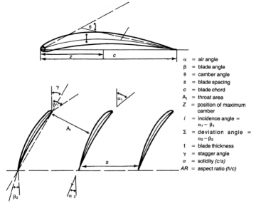
This equation can be written in the form: Equation-1.2 (see Figures 1.2.2 and 1.2.3 illustrating impeller velocity triangles), Figuer1.2.2 -Inlet velocity triangles for centrifugal compressor impeller, Figuer1.2.3 - Exit velocity triangles for centrifugal compressor impeller. Why the change to axial compressors? For clarification during compressor familiarization, the units are treated individually. For example, at 100% RPM stalling flow might increase from approximately 0.170kg/s to 0.215kg/s because of the positive slope of the pressure ratio curve. The doors are held closed by spring action when the engine is not operating. another impeller or a combustor, flow losses can be reduced by directing the flow with stationary turning vanes or individual turning pipes (pipe diffusers). Professional societies such as ASME (i.e. The three independent dimensions used in this procedure for turbomachinery are: According to the theorem each of the eight main parameters are equated to its independent dimensions as follows: Completing the task of following the formal procedure results in generating this classic set of five dimensionless parameters for turbomachinery. The next feature to be discussed is the oval-shaped curves representing islands of constant efficiency. (adsbygoogle = window.adsbygoogle || []).push({}); The centrifugal-flow compressor consists of an impeller (rotor), a diffuser (stator), and a compressor manifold. These blow-in doors admit air to the engine compartment during ground operation, when air requirements for the engine are in excess of the airflow through the inlet ducts. Again, the horizontal axis represents the energy equation with turbines generating power to the left and compressors absorbing power to the right. Also, they often experience relative fluid velocities above Mach number 0.3[20] when the working fluid is air or nitrogen. A diagonal stage is used in the Pratt & Whitney Canada PW600 series of small turbofans. In general application, the Flow-coefficient and Head-coefficient are considered of primary importance. When the diffuser discharges into an annular bend the collector may be referred to as a combustor inlet (as used in jet engines or gas turbines) or a return-channel (as used in an online multi-stage compressor).
+ Equal Employment Opportunity Data Posted Pursuant to the No Fear Act
{\displaystyle T} In contrast, all volume flow specifications require the additional specification of density. As working-gas/flow passes through the impeller from stations 1 to 2, the kinetic and potential energy increase. [Figure 1-46] Centrifugal compressors have a high pressure rise per stage that can be around 8:1. C Figures 1.1 and 1.2 illustrate the domain of turbomachinery with labels showing centrifugal compressors. is the internal energy per unit mass (the "specific internal energy"), Centrifugal compressors also look very similar to their turbomachinery counterpart the radial turbine as shown in the figure. The principal differences between the two types of impellers are size and ducting arrangement. When the diffuser discharges into a large empty circumferentially (constant area) chamber, the collector may be termed a Plenum. [1][14] It is implied that mixed-flow turbomachinery lie between axial and radial. In many cases, the engineering methods used to design a centrifugal fan are the same as those to design a centrifugal compressor, so they can look very similar.
Many industrial and commercial multistage compressor performance maps exhibits this same vertical characteristic for a different reason related to what is known as stage stacking. It then flows through a stationary compressor causing it to decelerate. It may be found interesting that the Speed-coefficient may be chosen to define the y-axis of Figure 1.1, while at the same time the Reynolds coefficient may be chosen to define the z-axis.
Compared to estimating performance which is very cost effective (thus useful in design), testing, while costly, is still the most precise method. Assuming dry air, and the ideal gas equation of state and an isentropic process, there is enough information to define the pressure ratio and efficiency for this one point. When placed in a different system those lower flows might not be achievable because of interaction with that system. air compressor centrifugal gas impeller pressure compressors principles turbines weebly The two main functional elements are the impeller and the diffuser. 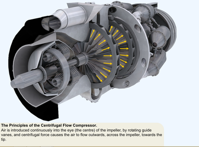 In engineering situations assuming adiatice flow, this equation can be written in the form: The identifying component of a centrifugal compressor stage is the centrifugal impeller rotor.
Historically, centrifugal compressors applied to industrial applications were needed to achieve performance at a specific flow and pressure.
While a compressor transfers energy into a flow to raise its pressure, a turbine operates in reverse, by extracting energy from a flow, thus reducing its pressure. + The President's Management Agenda turbine engines use multi staged axial compressors. These cyclic events cause large vibrations, increase temperature and change rapidly the axial thrust. turbojet and In most cases the reason for this is that close to Mach 1 velocities have been reached somewhere within the impeller and/or diffuser generating a rapid increase in losses.
is temperature and
impeller pratt centrifugal apu whitney and Of particular interest, is that while turbomachines may be very durable, their physical system can be far less robust.
The above equation is known as the fundamental thermodynamic relation. Centrifugal compressors, which General standard practice is to interpret these efficiencies as isentropic rather than polytropic. For younger students, a simpler explanation of the information on this page is
Included in some installations as necessary parts of the plenum chamber are the auxiliary air-intake doors (blow-in doors). In engineering situations assuming adiatice flow, this equation can be written in the form: The collector of a centrifugal compressor can take many shapes and forms. but all turbine engines have some parts in common.
These air outlets are constructed in the form of ducts and are known by a variety of names, such as air outlet ducts, outlet elbows, or combustion chamber inlet ducts. For purposes of generalization and definition, it can be said that centrifugal compressors often have density increases greater than 5 percent. Centrifugal compressors are also similar to centrifugal pumps[1] of the style shown in the adjacent figures. The fifth parameter, specific diameter, is a less often discussed dimensionless parameter found useful by Balje.[38]. The method of procedure known as the Buckingham theorem can help solve this problem by generating 5 dimensionless forms of these parameters. {\displaystyle \delta Q=TdS}
[clarification needed], From the very start of the aero-thermodynamic design process, the aerodynamic considerations and optimizations [29,30] are critical to have a successful design. Regardless of the terminology used, these outlet ducts perform a very important part of the diffusion process; that is, they change the radial direction of the airflow to an axial direction, in which the diffusion process is completed after the turn.
 While flow measurements use a variety of units, all fit one of 2 categories: Mass flow units, such as kg/s, are the easiest to use in practice as there is little room for confusion. These requirements are of secondary importance to the overall gas turbine performance as a whole. As turbomachinery became more common, standards have been created to guide manufacturers to assure end-users that their products meet minimum safety and performance requirements. The double-entry type has a smaller diameter, but is usually operated at a higher rotational speed to assure sufficient airflow. Despite this complexity, a few basic concepts in performance can be presented by examining an example test performance map.
Selecting a low efficiency (<60%) is the most common practice used to terminate compressor performance maps at high flows.
Impellers are designed in many configurations including "open" (visible blades), "covered or shrouded", "with splitters" (every other inducer removed), and "w/o splitters" (all full blades). [1][14] Key contributors of technical achievements that pushed the practical application of turbomachinery forward include:[15][16] Denis Papin,[17] Kernelien Le Demour, Daniel Gabriel Fahrenheit, John Smeaton, Dr. A. C. E. Rateau,[18] John Barber, Alexander Sablukov, Sir Charles Algernon Parsons, gidius Elling, Sanford Alexander Moss, Willis Carrier, Adolf Busemann, Hermann Schlichting, Frank Whittle and Hans von Ohain. Under critical conditions, the flow will reverse back over the tips of the rotor blades towards the impeller eye (inlet). [36] At low flow rate operation, the pressure ratio over the impeller is high, as is back system backpressure.  blade nomenclature turbofan blades file airfoil wikipedia found lcas As a test map, these points would be the lowest flow points possible to record a stable reading within the test facility/rig. performance.
This is due to requiring fewer stages to achieve the same pressure rise.
They may include other components such as an inlet throttle valve, a shrouded port, an annular duct (see Figure 1.1), a bifurcated duct, stationary guide vanes/airfoils used to straight or swirl flow (see Figure 1.1), movable guide vanes (used to vary pre-swirl adjustably). In contrast, fans or blowers are often considered to have density increases of less than five percent and peak relative fluid velocities below Mach 0.3. perpendicular to the axis of rotation. There is a variety of pressure measurement units. is the specific heat at constant volume, and [5] incoming air before it enters the combustor. through the compressor travels parallel to the axis of rotation. and Accessibility Certification, + Equal Employment Opportunity Data Posted Pursuant to the No Fear Act, + Budgets, Strategic Plans and Accountability Reports, This page is intended for college, high school, or middle school students. [1] Full-similitude is achieved when each one of the 5 Pi-parameters is equivalent when comparing two different cases. This assumption is not acceptable in practice as inlet temperature variations cause significant variations in compressor performance. [1][14] The Z-axis differentiates between axial-flow geometry and radial-flow geometry within the physical domain of turbomachinery. Figure 2.2 (shown right) represents the physical or mechanical domain of turbomachinery. Written in compressible form for a Newtonian fluid, this equation may be written as follows: The first law of thermodynamics is the statement of the conservation of energy. [1][14] Within the physical domain the vertical axis differentiates between high speeds and low speeds depending upon the turbomachinery application. These types of plots are fundamental to understanding centrifugal compressor performance at one operating point. Figure 5.2, a centrifugal compressor performance map (either test or estimated), shows the flow, pressure ratio for each of 4 speed-lines (total of 23 data points).
Refer to Figure 1-46A and note the arrow indicating the path of airflow through the diffuser, then through the manifold. engines usually use axial compressors.
In some applications, collectors will diffuse flow (converting kinetic energy to static pressure) far less efficiently than a diffuser.[6]. When large enough, rapid flow reversal occurs(i.e., surge). When reversed flow reduces to a low enough level, the impeller recovers and regains stability for a short moment at which point the stage may surge again. A substantial portion of this energy is kinetic which is converted to increased potential energy/static pressure by slowing the flow through a diffuser. has a large influence on total engine
 Also termed continuity, this fundamental equation written in general form is as follows: Also termed the NavierStokes equations, this fundamental is derivable from Newton's second law when applied to fluid motion. Although slightly more efficient in receiving air, the singleentry impeller must be large in diameter to deliver the same quantity of air as the double-entry type. The diffuser vanes direct the flow of air from the impeller to the manifold at an angle designed to retain the maximum amount of energy imparted by the impeller. For the example below Head will be substituted for pressure and sonic velocity will be substituted for elasticity. = Diffusers can be vaneless, vaned, or an alternating combination. 2007, American Society of Heating, Refrigeration, and Airconditioning Engineers, International Organization for Standardization, Reynolds-averaged NavierStokes equations, Three-dimensional losses and correlation in turbomachinery, "Genetic Algorithm Optimization of the Volute Shape of a Centrifugal Compressor", "From the Crystal Palace to the pump room", "Description 2021 ASHRAE HandbookFundamentals", "Flow phenomena leading to surge in a centrifugal compressor". Further, testing centrifugal compressor performance is very complex. +
Centrifugal compressors are also similar to centrifugal fans of the style shown in the neighboring figure as they both increase the energy of the flow through the increasing radius. Rather, improvements have been achieved through understanding and applying incremental pieces of knowledge discovered by many individuals. The classical ideal gas law may be written: The ideal gas law may also be expressed as follows. [10][citation needed] The first part of the centrifugal impeller looks very similar to an axial compressor. According to a form of Euler's fluid dynamics equation, known as the pump and turbine equation, the energy input to the fluid is proportional to the flow's local spinning velocity multiplied by the local impeller tangential velocity. In the case where flow passes through a straight pipe to enter a centrifugal compressor, the flow is axial, uniform, and has no vorticity, i.e. The key difference between such compressors and pumps is that the compressor working fluid is a gas (compressible) and the pump working fluid is liquid (incompressible). The map shown in Figure 5.2 illustrates the most common method; lines of constant speed. Text Only Site
Also termed continuity, this fundamental equation written in general form is as follows: Also termed the NavierStokes equations, this fundamental is derivable from Newton's second law when applied to fluid motion. Although slightly more efficient in receiving air, the singleentry impeller must be large in diameter to deliver the same quantity of air as the double-entry type. The diffuser vanes direct the flow of air from the impeller to the manifold at an angle designed to retain the maximum amount of energy imparted by the impeller. For the example below Head will be substituted for pressure and sonic velocity will be substituted for elasticity. = Diffusers can be vaneless, vaned, or an alternating combination. 2007, American Society of Heating, Refrigeration, and Airconditioning Engineers, International Organization for Standardization, Reynolds-averaged NavierStokes equations, Three-dimensional losses and correlation in turbomachinery, "Genetic Algorithm Optimization of the Volute Shape of a Centrifugal Compressor", "From the Crystal Palace to the pump room", "Description 2021 ASHRAE HandbookFundamentals", "Flow phenomena leading to surge in a centrifugal compressor". Further, testing centrifugal compressor performance is very complex. +
Centrifugal compressors are also similar to centrifugal fans of the style shown in the neighboring figure as they both increase the energy of the flow through the increasing radius. Rather, improvements have been achieved through understanding and applying incremental pieces of knowledge discovered by many individuals. The classical ideal gas law may be written: The ideal gas law may also be expressed as follows. [10][citation needed] The first part of the centrifugal impeller looks very similar to an axial compressor. According to a form of Euler's fluid dynamics equation, known as the pump and turbine equation, the energy input to the fluid is proportional to the flow's local spinning velocity multiplied by the local impeller tangential velocity. In the case where flow passes through a straight pipe to enter a centrifugal compressor, the flow is axial, uniform, and has no vorticity, i.e. The key difference between such compressors and pumps is that the compressor working fluid is a gas (compressible) and the pump working fluid is liquid (incompressible). The map shown in Figure 5.2 illustrates the most common method; lines of constant speed. Text Only Site
They achieve pressure rise by adding energy to the continuous flow of fluid through the rotor/impeller. For these reasons, most high performance, high compression For example, centrifugal compressors used for large air conditioning systems (water chillers) use a refrigerant as a working gas that cannot be modeled as an ideal gas. C Under specific conditions, the operation of a Centrifugal compressor is considered a reversible process. is the specific heat at constant pressure. This is a situation where the pressure ratio of a speed line drops rapidly (vertically) with little or no change in flow. were used in the first jet engines, are still used on small turbojets
To find API codes, standards & publications, To find ASME codes, standards & publications, To find ASHRAE codes, standards & publications, Hydrodynamics of Pumps, by Christopher Earls Brennen, Ctrend website to calculate the head of centrifugal compressor online, Electronic centralised aircraft monitor (ECAM), Electronic flight instrument system (EFIS), Engine-indicating and crew-alerting system (EICAS), Full Authority Digital Engine/Electronics (FADEC), https://en.wikipedia.org/w/index.php?title=Centrifugal_compressor&oldid=1096680230, Articles with dead external links from July 2020, Articles with permanently dead external links, Articles with unsourced statements from December 2021, Wikipedia articles needing clarification from September 2016, Creative Commons Attribution-ShareAlike License 3.0, Frank Whittle and Hans von Ohain, independently, First gas turbine using a centrifugal compressor, 3D-CFD, rocket turbo-pumps, heart assist pumps, turbocharged fuel cells, In industry and manufacturing to supply compressed air for all types of.
As stated earlier, the reason for this is that the high-speed line in Figure 5.2 exhibits a stalling characteristic or positive slope within that range of flows.