Thanks for the great feedback! The speed of the turbine wheel has a direct relation with the speed of the flow of water through the water flow sensor. Did you try the sensor with 3.3V? For example, whenever a pulse occurs on the output pin, the output signal goes from active low to active high state which is also known as a positive or rising edge of the pulse as shown in the figure below: We can count these rising edges with the help of one of the interrupt pins of Arduino. For example (10 ml) and this to water(spray). remove the next two lines and just divide flowRate by 1000. how can i print how many liters passed in the sensor and how to print it on LCD? If you are using a different Arduino please consultthis tableto see what pins are available! Could you help me? Would that be possible with this setup? Get notifications of our upcoming sales, holiday hours, and new products delivered directly to your inbox! Adafruit Industries is an American supplier of high quality electronic kits and components based in New York city. I have looked, but i cant really find anything about it, or is there any other way to do this? Arduino is the most popular open source microcontroller platform on the market. We carry a variety of Arduino starter kits to get you reading sensors and blinking lights as easily as quickly as possible! The void loop will determine the flow rate by counting the frequencies or pulses every second. This type of flow sensor is designed to measure the volume of liquid traveling past a given point, a great way to keep tabs on how much water your drip irrigation system is using, or any other project were the flow of liquid needs to be tracked. Code can be designed using a drag and drop interface in the Blocks editor, Javascript, or Python. In general, you can use the following formula: Q is the flow rate (e.g. Projects like a Banana Drum Set, Cat Detector, Musical Stairs, and countless others are easier than you think! On the following line we delay the code for 1000ms (1 Second) to give us time to count pulses and on the last line we disable the interrupts to stop counting. The electric pulse will be generated due to the flow. This water flow sensor consists of a water rotor (turbine wheel) and a Hall effect sensor. These easy to program devices can read sensors, control relays, light up LEDs, and even talk to one another. What if you want to print the output on an LCD? If you know how I can catch this would appreciate a reply. I am not sure if this is something you know or not but I thought I would ask. In addition to this, it also contains an internal circuit of the Hall effect sensor that works on the principle of electromagnetism and provides pulses at the output pin.  In other words, the number of pulses that appear on the signal output pin is directly proportional to the rotational speed of the turbine. Delay is simple and it does exactly what it says it does writing better non-blocking code is a concept that can be learned later and isnt terribly relevant to getting the basic sensor working . Could you help me about code ? We chose this method as it is much easier to visually follow the wires. Hence: In this section, we will see how to display measured water flow rate value on 162 LCD. What if i use Pull down resitor 10K ohm and set attachInterrupt Save my name, email, and website in this browser for the next time I comment. Could I use this code for my research purpose? Let us discuss the pinout of the YF-S201 Water Flow Sensor. Maybe try using a pressure sensor instead. attachInterrupt (2, Flow, RISING); [/cpp], You just solved a big problem for me, with a very simple way, thanks man, i think i may have looked at it like it was way more complicated than it really is, again thanks . Helo sir can i get a code that helps the flow sensor to read the flow of pressure passing through the valve ( i mean like if the valve is completely open the sensor will detect full pressure and give out a reading of 100% likewise if its half open the sensor will detect from the pressure and give out a reading for 50% also respectively for 75% and 25%. We have been a supplier of SparkFun in Canada since 2015 and continue to expand our collection of their fine products! The microcontroller is programmed using the Arduino IDE. As soon as the pulse is detected, the attachinterrupt will call the subroutine and count the pulses in the flow_frequency variable. If yes then how? Is it correct? SparkFun products in our shop: 1 x Arduino Uno or compatible microcontroller, Hookup Wires - We recommend Premium Male/Male Jumper Wire. flowRate = flowRate * 60; //Convert seconds to minutes, giving you mL / Minute Observe that when no water is flowing through the water sensor Rate: 0 L/M and vol: 0.0 L will be displayed on the screen as well as the serial monitor. This tutorial will be requiring a few common parts: This handy little diagram shows how we will be connecting everything. to trigger when input pin is FALLING ? We have one last wire to add this connects the pull up resistor and the sensor output to the Arduinos digital input. I wanted to measure volume of fluid (like grease or peanut butter) which is having the viscosity of 2,90,000 cps flowing through a pipe. You will see the measured values on serial monitor as shown below: The maximum portion of the Arduino code is self-explanatory except for the calculation part of the water flow rate in this line: As you know that the pulse_count variable contains the number of pulses in one second which is generated by the output pin of the water flow sensor. As the water flow sensor is compatible with microcontrollers, we can observe the measurements on a computer serial monitor and can also display them on 162 LCD.
Where are you trying to log the data? So your other choice is pin 3. { But their working principle and the procedure to interface with microcontrollers such as Arduino remains the same. I was looking for such a project for my hydroponic system. Trying to seek resolution. One way to avoid this problem is good wire color discipline. According to the datasheet, frequency is calculated by multiplying the flow rate by 7.5. Any explanation? However, if I turn on or off one of the switches on the wall panel ( like my laundry room light) then it triggers false pulses to the USB adapter that is connected to the Microcontroller. Can u make using pic18 family microcontroller, How to make an alarm when the circulation of liquid is stopped, so that, for example, turn off a pump or a computer (ifwe use water cooling of the processor), Can you help with connecting a Flow meter to an 12864 I2cOLED display. I am new for arduino and i couldnt find any code like that. Since 2005 Adafruit has provided parts for all skill levels and coupled them with detailed tutorials, source code, project videos, and examples. Haha i always wanted a hose speedometer Your Water Speed is: . I need to use water flow sensors for science fair and I was wondering if its possible to connect multiple sensors? If I wanted to have a set volume that I wanted to send through the flowmeter, would I have to put the counter in a for loop to reach the desired pulses then perform another action once that for loop was finished? 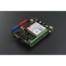 The YF-S201 is known as a Hall effect sensor because it operates on the Hall effect. That way I can understand what type of storage I should be looking into. The BBC micro:bit is a pocket-sized computer designed for beginners in electronics and coding. Have a great day.
We can program one of the interrupt pins in such a way that whenever a rising edge occurs, the interrupt is triggered. We have seen the same sensor with both 450 pulses per liter and 2.25mL / pulse numbers thrown around. //Your system stopped flowing water and didnt run a full duration After 100ml, valve closes. The Adafruit Feather line of Arduino compatible microcontrollers are designed with battery power and portability in mind. The number of liters would actually be simpler, flowRate = (count * 2.25); // gives you the total during the period of time measured. Now make the connection with water flow sensor and Arduino according to this schematic diagram: This Arduino sketch for the water flow sensor measures the water flow rate in units of a liter per hour and displays the measured value on the serial monitor of Arduino IDE.  The speed interferes with the magnetic flux which is sensed by the Hall effect sensor and the sensor in returns generates an output signal proportional to the magnetic flux with every revolution that the rotor makes. I managed to walk the sensor and write on an LCD the instantaneous flow. These thin form factor Arduinos have a built in single cell lithium charge circuit built right in just plug in a LiPo battery and off you go! It explores the concepts of creating circuits through everyday items. Since the loop runs over and over again we need reset our variable count to 0 at the beginning, we do not want the number of pulses from the last loop carrying forward. It was created to make getting into these often daunting fields as easy as possible. Where do you get 2.25mL that would be 5 rotations according to your data. Read our privacy policy for more info. When I enable my interrupts only the last interrupt get the pulse ? noInterrupts(); //Disable the interrupts on the Arduino, Serial.println(flowRate); //Print the variable flowRate to Serial Now I would like to add the measurement of the VOLUME of water that was circulating and I can not think of what line of code to add. Water enters through of end and leaves through the other end of the sensor. count++; //Every time this function is called, increment count by 1 Like you say, there is a limited number of writes that each EEPROM address can take so if this power down would happen often, Id suggest using data logging instead (saving data to and SD card for example, and then retrieving it from there). Its multitude of inputs and outputs for electronics and computer peripherals and its impressive computing power mean it can be used to make just about anything you can imagine. According to the datasheet of YF-S201 Water Flow Sensor, the output pulse frequency can be calculated with this equation: The above equation can also be written as: Here pulse frequency is the number of pulse count in one minute. After that we attach the interrupt 0 with digital pin D2 and also passes the address of callback function (Detect_Rising_Edge) which will execute every time interrupt occur due to rising edge on D2 pin. 1000/450= 2.25mL. We have carried the Raspberry Pi in Canada since it first became available and have watched as the Pi has morphed into a complete development platform with powerful single-board computers, cameras, touchscreens, and other accessories. Time (revolution time) and Distance (circumference) will give you Speed. I can only bash my face on the keyboard for so long.
So, what is the best way to count RPM with an Arduino? I added the Pull down resistor 10k between the Vcc and the signal as you suggested, Still I am seeing some pulses when I turn on off switch next door to where the microcontroller is connected via the USB adapter. What is the code for that.
Your email address will not be published. Next, run a wire from the Ground pin on the Arduino over to the negative rail on the solderless breadboard. BC Robotics Inc. is a Canadian owned electronics company based in Nanaimo, British Columbia. Arduino provides two external interrupt pins such as Digital I/O Pins 2 and 3. In this case the interrupt pin is going to be very useful. We will be using the Arduino IDE, this is available fromhttps://www.arduino.cc/en/Main/Software. Now that all of the code has been written it can be uploaded to your Arduino! Should I use ESP8266 digital pin (GPIO2) as input pin and in attachInterrupt function? When the fluid flows through, it rotates the rotor which has a magnet attached to it. Hence, we can measure the water flow rate by measuring the number of pulses sensors produce in one second or in one minute. In short, we can use YF-S201 water flow sensor with any microcontroller such as Arduino, Raspberry Pi, Pic microcontroller, 8051 microcontroller, STM32 Blue Pill, ESP32, ESP8266 to measure water flow rate. void loop() { Best of all, Feathers are available with a variety of chipsets and built in wireless modules there is an Adafruit Feather for every project! It can certainly be done but youd need a backup power source to write to the EEPROM only when it detects a power down (unless the power down is planned, like pushing a button then you can write a shutdown routine that writes to the EEPROM before it powers down the chip; youll probably need to use additional electronic components too). Knowing that there are 450 pulses per liter, we can then determine the flow rate over time or the total volume that has passed or both! The loop compares the current time with the starting time and exits when it reaches a set value. Could we juste reajuste the *2.25? Since its release, well over 30 million of these little computers have been sold. Water Flow Sensor Interfacing with Arduino, ESP32 MQTT Publish Subscribe DS18B20 Readings with Arduino IDE, ESP32 MQTT Publish Subscribe BME280 Readings with Arduino IDE, ESP32 MQTT Publish Subscribe DHT22 Readings with Arduino IDE, Install Node-RED on Raspberry Pi (32-bit and 64-bit RPI OS), ESP RainMaker Getting Started Tutorial with ESP32 and Arduino IDE. In the end, we will see how to interface the YF-S201 Water flow sensor with Arduino and its programming in Arduino IDE. pinMode(flowPin, INPUT); //Sets the pin as an input Detect_Rising_Edge() function is the interrupt function that is used to count the pulses generated by the Hall effect sensor. Thanks for a wonderful explanation. Why not use pinMode(flowPin, INPUT_PULLUP) instead of a 10 ohm resistor on the signal wire? Time to start writing the main code that will run continuously in the loop: OK, half way there. We are going to jump right in and set up the Arduino Uno and the breadboard right next to one another. flowPin = 2; The NVIDIA Jetson Nano is an in-expensive, high performance, single board computer developed specifically with artificial intelligence applications in mind. Very concise and easy to understand. To better illustrate how this line works, think of it as this: attachInterrupt(interrupt number, the function you would like to run when triggered, what you would like to set as the trigger). else { The attachinterrupt is responsible to keep a check on the pulses. The wire configuration detail in tabular is mentioned below:Pin NumberPin NameFunction1REDPositive supply wire2BLACKGround wire3YELLOWOutput Voltage wire.
Output voltage wire(yellow) to digital pin D2 of the Arduino to detect the electric pulses. if (flowRate > (0 + flowBuffer)) Yes, you most certainly can but you will be limited by the number of interrupt pins on your microcontroller. I believe that you can attach an interrupt to any digital pin on the ESP8266. Thanks. For more information on Arduino interrupts, you can refer to this article: In this example, we will use digital I/O pin 2 of Arduino as an external interrupt capture pin to count the number of pulses. Can you tell me where I went wrong.thanks just a newbie here.Still dont have a concept on how or how to apply a code to every day living. Great sketch. Before we give the Arduino power it is always a good idea to go over all of the connections to make sure there are no wires in the wrong spot sometimes that can make for a very expensive mistake! Each revolution you will see the voltage on the sensor output transition from HIGH to LOW and back to HIGH again so you can monitor the falling or rising event you will still get the same count. After the execution, the MCU will reset the counter and is ready for the next calculations. Connect the power supply pins of the YF-S201 water sensor to the ground and 5 Volts pins of the Arduino. Just curious, regarding the interrupt configuration attachInterrupt(0, Flow, RISING). while volume < threshold Interrupts are complicated enough for beginners as is so we dont really need to be explaining the millis() function and conditional statements, all at the same time. Microcontrollerslab.com All Rights Reserved.
As a result, the LCD will display zero that means no water flow was sensed at a particular time. Can I simply have several sensors each sending signals to a different interrupt pin? I want to write to EEPROM when the Arduino detects power down Im not sure it is ok because EEPROM cycle use is limited. }
The flow rate is stored in vol and will be displayed on the LCD. This section deals with the interfacing of an Arduino microcontroller to the YF-S201 Water Flow Sensor. We know from theproduct pagethat the red wire is a power wire, the yellow wire is the output wire for the sensor, and the black wire is a ground. Make some water flow through the sensor. It is a power-friendly and MCU compatible device with a flow rate of a maximum of 30 liters per minute. After that open the serial monitor and set the baud rate to 9600. That is: Hi, great explanation about using interrupts. We will want it to increment every single time there is a pulse received which means we need to create a new function that the interrupt will run when a pulse is received: The ++ following the variable means every time the program runs this line it will add 1 to that variable great for counting! The next line enables the interrupts, meaning we now start counting how many pulses the sensor sends out. The pull up resistor prevents a situation where the Arduino digital input pin ends up floating (think of this as the input not definitively being on or off). The Makey Makey kit is a electronics kit designed for beginners. int flowPin = 2; //This is the input pin on the Arduino Now that we have finished with the hookup we need to start writing some code. Start by connecting one of the jumper wires from the 5V pin on the Arduino and running it over to the positive rail on the side of the solderless breadboard. If you dont know how to interface a 162 LCD with Arduino, you can check this guide: Now make connections with Arduino, water flow sensor and 162 LCD according to this schematic diagram:16X2 LCDArduinoD4 D79, 10, 11, 12E7RS4VEEPOT (Middle Leg)VSSGroundVDD+5VD++5VD-Ground, Connections with Arduino and water flow sensor:ArduinoWater Flow SensorD2Signal Output5VVCCGNDGND.